Project Log: Saturday, August 11, 2012
Next on the agenda was to complete the installation of
the exhaust and air intake system for the diesel heating
system. My plans in this direction had been
stymied a bit earlier when I found that one of the
fittings I'd ordered in advance was the wrong size, but with the
correct fitting now on hand and no particular reason not to
proceed, it was time to knock this off the list.
I'd oriented the boiler in such a way as to make the
exhaust run in particular as straight and simple as
possible, as I had the least leeway in its routing and
design, and knew that the exhaust outlet would
necessarily end up somewhere aft and high up on the
hull. Exactly where would depend on many factors,
all of which I had to now consider and take into
account.
Practically speaking, the first consideration was access
for installing the exhaust and intake fittings and
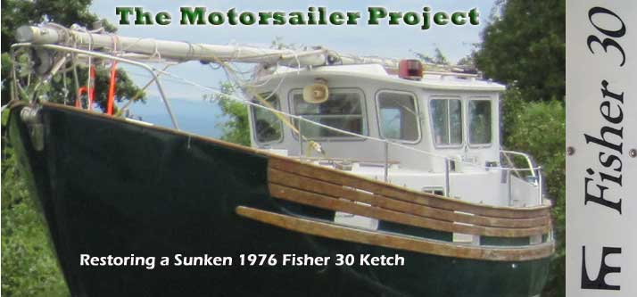
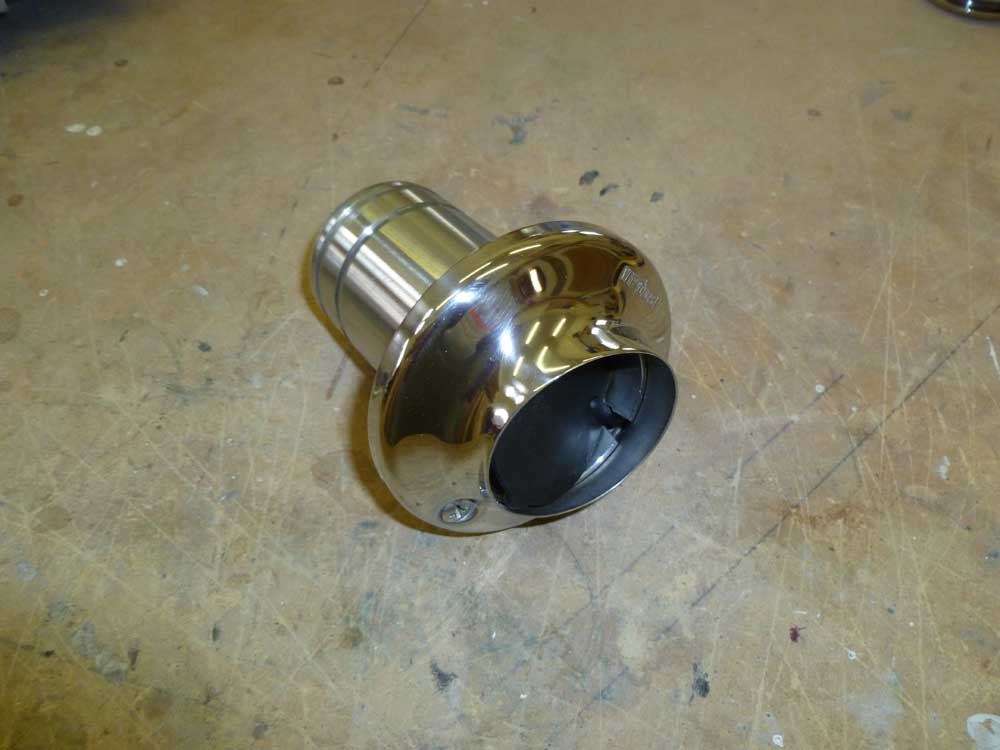
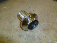
piping as required. The exhaust fitting was a
special double-walled fitting incorporating a 90° bend
on the inside, which I'd specified since I planned to
install the fitting in the space outboard of the cockpit
coaming, where the angled fitting would provide the
cleanest run for the exhaust piping. In
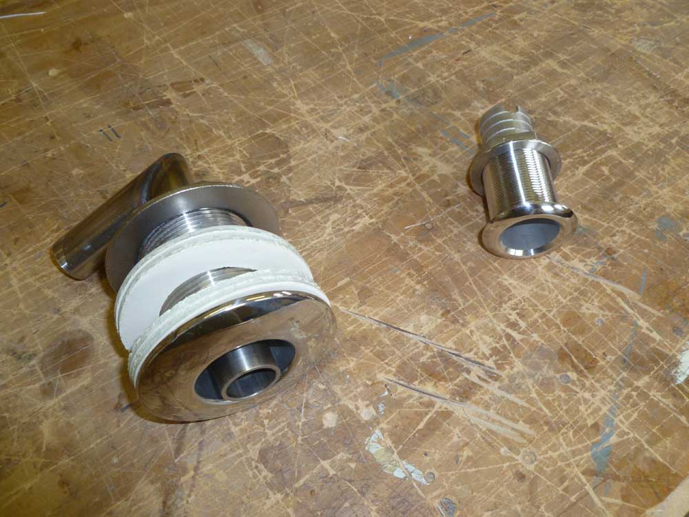
addition, there were four rings of a special insulating
material, two for outside and two for inside, plus a
smaller spacer ring that would hold the fitting in the
center of its slightly-oversized installation hole to
prevent contact of the metal with the hull.
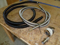
The intake fitting was nothing unusual; a plastic
through hull would have worked fine, but I chose a nice
stainless steel 1" through hull fitting instead.
The piping included 22mm stainless steel flex pipe for
the exhaust, and a double-walled fiber-type flex pipe
for the intake. |

 |
The overriding consideration, however, was safety.
The exhaust would be hot, and could damage things around
it or burn people. So appropriate clearances from
known or future installations were required. The
exhaust piping itself would be protected with thick heat
insulation, but even so I needed to ensure clearances
around the pipe. Fortunately, my proposed run
didn't require any passage through bulkheads or other
obstructions, with a generally clear run from the heater
to the general location of the outlet on the after part
of the port hull. The intake had no special
installation requirements, other than the piping needed
to be basically the same length as the exhaust pipe to
ensure proper combustion balance.
Finally, the intake and exhaust fittings were required
to be a minimum of 20" apart from one another, and the
exhaust at least 20" from any other opening.
With these significant considerations in mind, it was
time to determine the exact location of the fittings and
install them. I'd already selected the port
quarter of the hull, forward of the transom, both for
safety reasons and for access. With a 4" deck
access plate already cut in the inside wall of the
cockpit (I'd cut this long ago to provide necessary
access to chainplate and mooring bit fasteners), I
planned to install the heater fittings within reach of
this opening. Otherwise, there was no access to
this part of the inside of the hull. As it was,
the installation would take me to the far reaches of the
access afforded by this small opening, and the opening
allowed me to either view the fittings or put an arm in,
but not both at the same time. |
 |
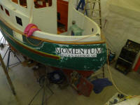
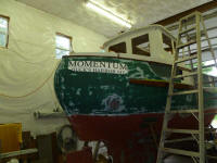
Of course this brought with it related complications:
namely the name. This section of the hull was
where I expected to apply the name and port, sometime
much later in the process, but the last thing I wanted
to do was install a fitting where it'd be in the way of
the graphics. So to help me sort out this
small--yet important--issue, I decided to first figure
out where the name was likely to end up, and how big it
was going to be.
A little work online gave me some estimated overall
lengths, depending on the letter height, but this was
too abstract, so instead I made up a pair of full-sized
mockups, choosing (somewhat randomly) a 4" height for
the name (2.5" for the port) and a basic Times Roman
font, both of which my sense told me were generally the
appropriate choices. The actual lengths of the
printed mockups were very close to the estimated
measurements I'd received from some online graphics
shop's software.
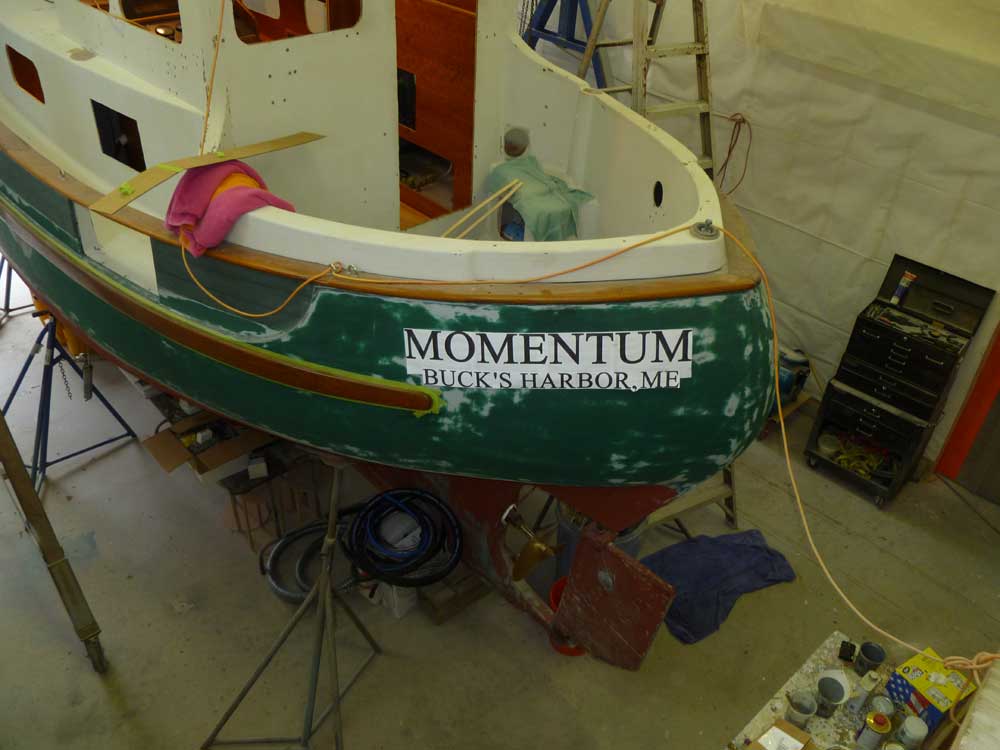
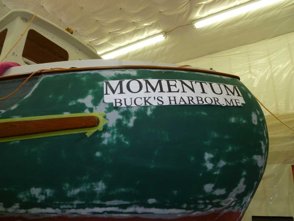
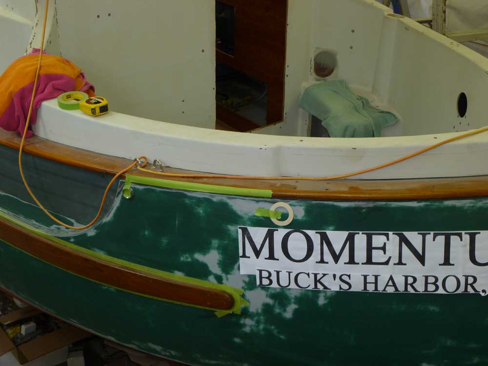
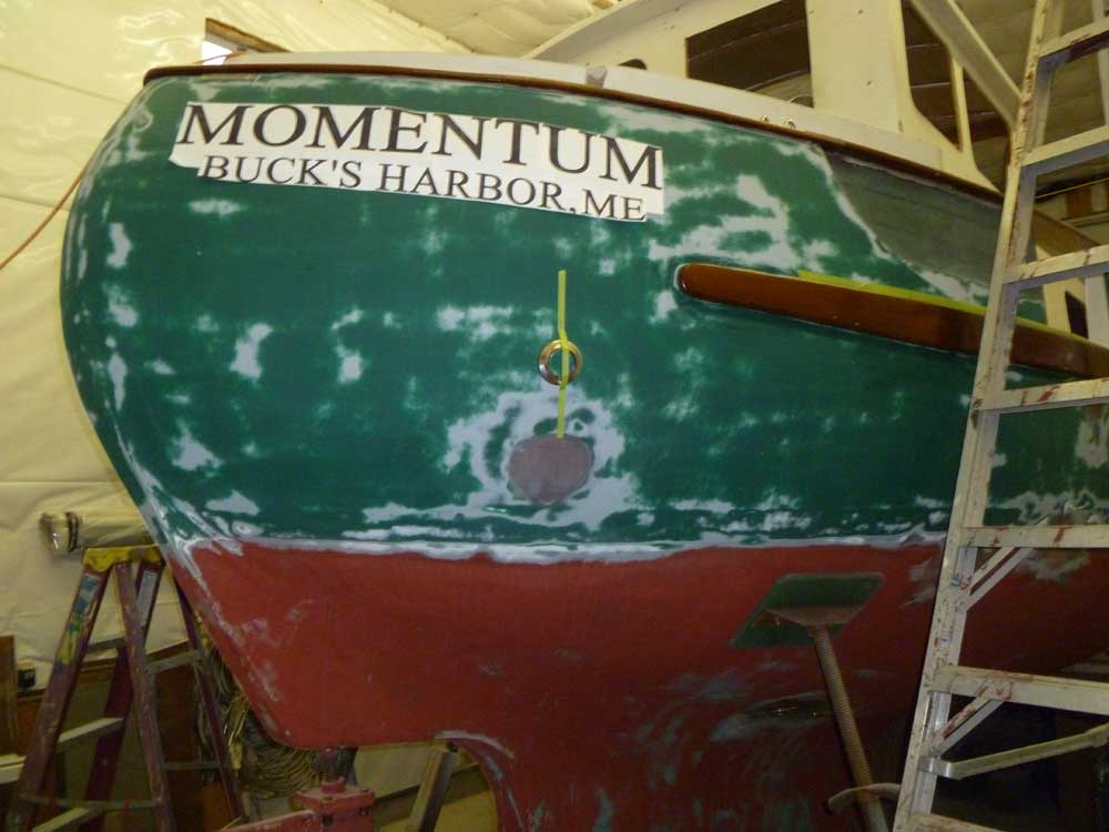
After eyeballing the space on the quarter, I made a few
reference marks, beginning with marks 4" down from the
caprail, which I thought would be about right for the
top edge of the name. From the center of the
transom, I marked a 10" space, randomly, to demark the
end of the graphics, then taped them up. I had to
start somewhere. |
 |
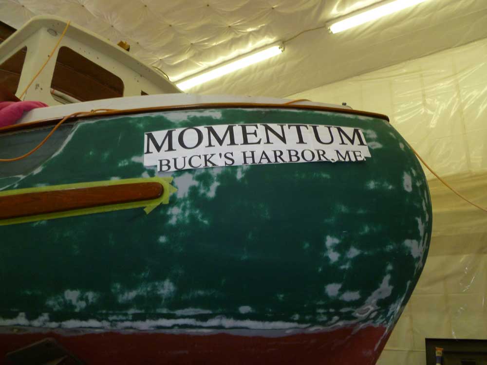
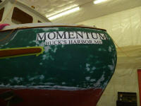
I thought the size seemed about right, but decided to
print out a 5" height version as well for comparison.
This was clearly too large: too long, too tall,
too crammed-looking, and just too bold.
|
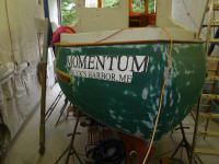 |
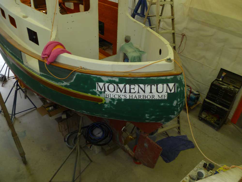
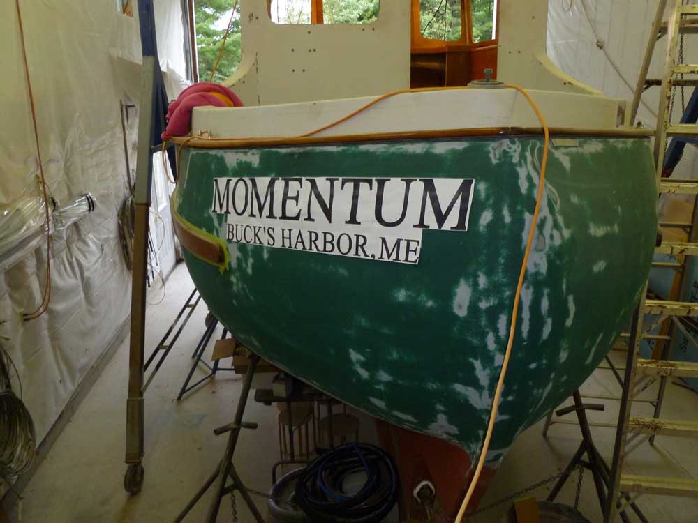
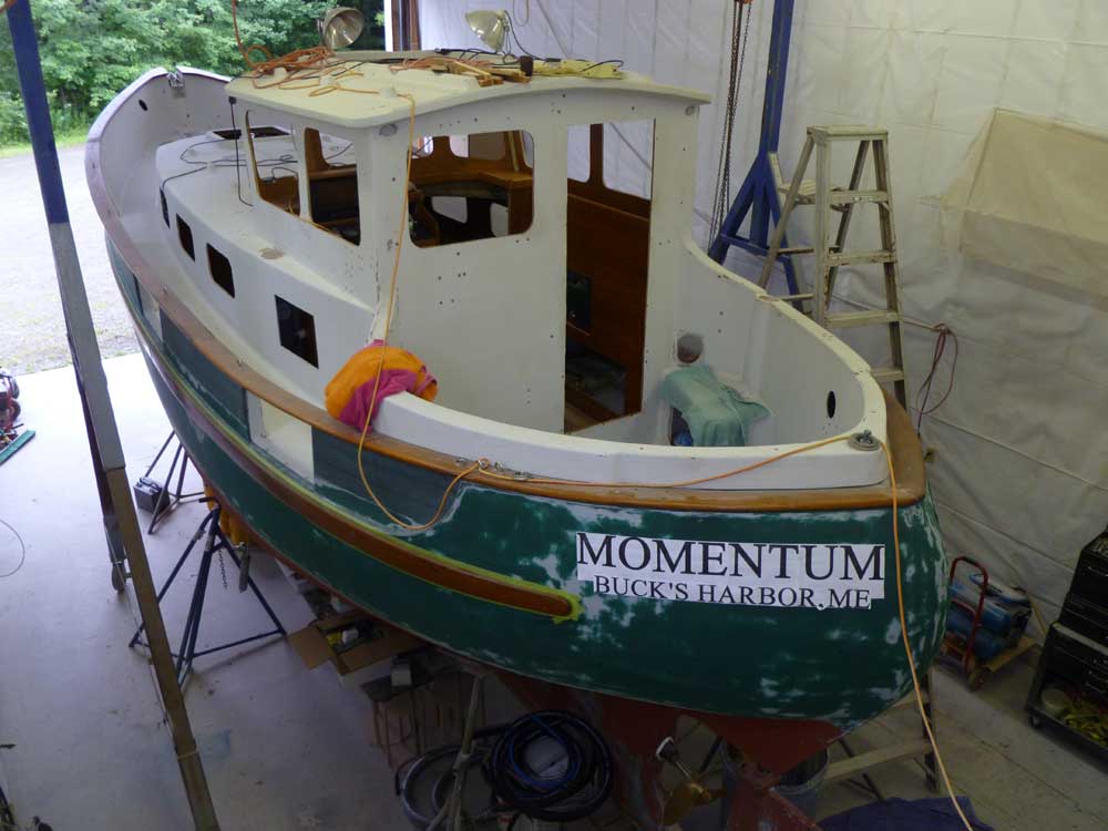
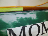
Returning to my 4" height, I made some minor adjustments
to the position. I liked the 4" distance from the
caprail, but the 10" spacing from the transom was too
much, and forced the first letters too far forward.
Spacing at the aft end was important, but I thought a
better reference point at the forward end would be a
vertical line extending from the end of the teak rubrail
on the hull, so with that I repositioned the graphics a
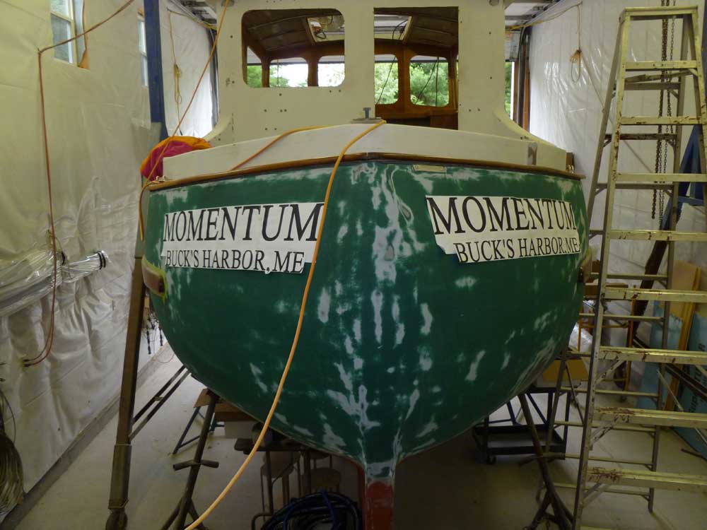
few inches further aft for consideration, repeating the
process on the starboard side to give me as many views
of the idea as possible. This was much better, to
my eye. |


 |
With this somehow frivolous tangent aside, I could move
on with the fittings' installation. To
begin, I used the backing nut from the intake fitting to
simulate its location on the hull, and located this as
far forward as I could before running into the molded
recess that would later accept the refinished bulwark
planking. I chose to locate the intake forward of
the exhaust since our typical usage of the boat,
specifically that we tend to swing on moorings or
anchors rather than slips, would mean that the intake
was upwind of the exhaust under normal circumstances.
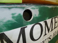
With a strip of masking tape cut to a strong 20", I
located the exhaust fitting, using one of the rings of
heat insulation as an analogue. This placed the
exhaust in the 4" band above the name, and somewhat
close to--but forward of--the location of the mooring
bit on the caprail, which was a potential concern since
I needed to ensure that I could later bolt that in
place. I kept the centers of the
dissimilarly-sized intake and exhaust fittings the same
distance from the caprail. |
 |
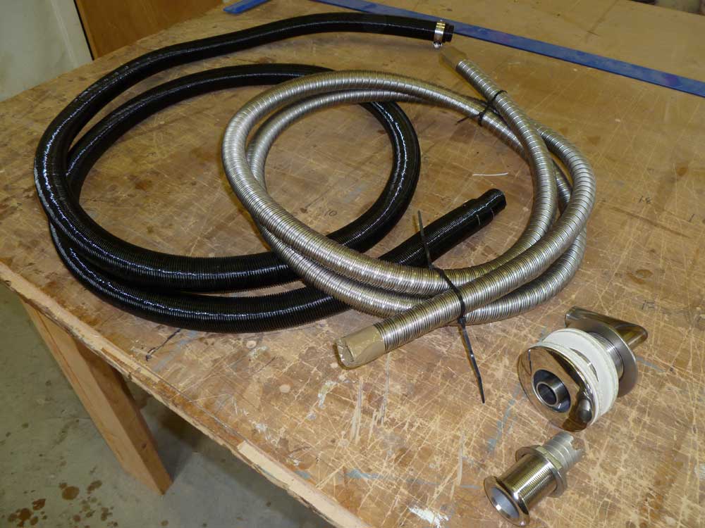
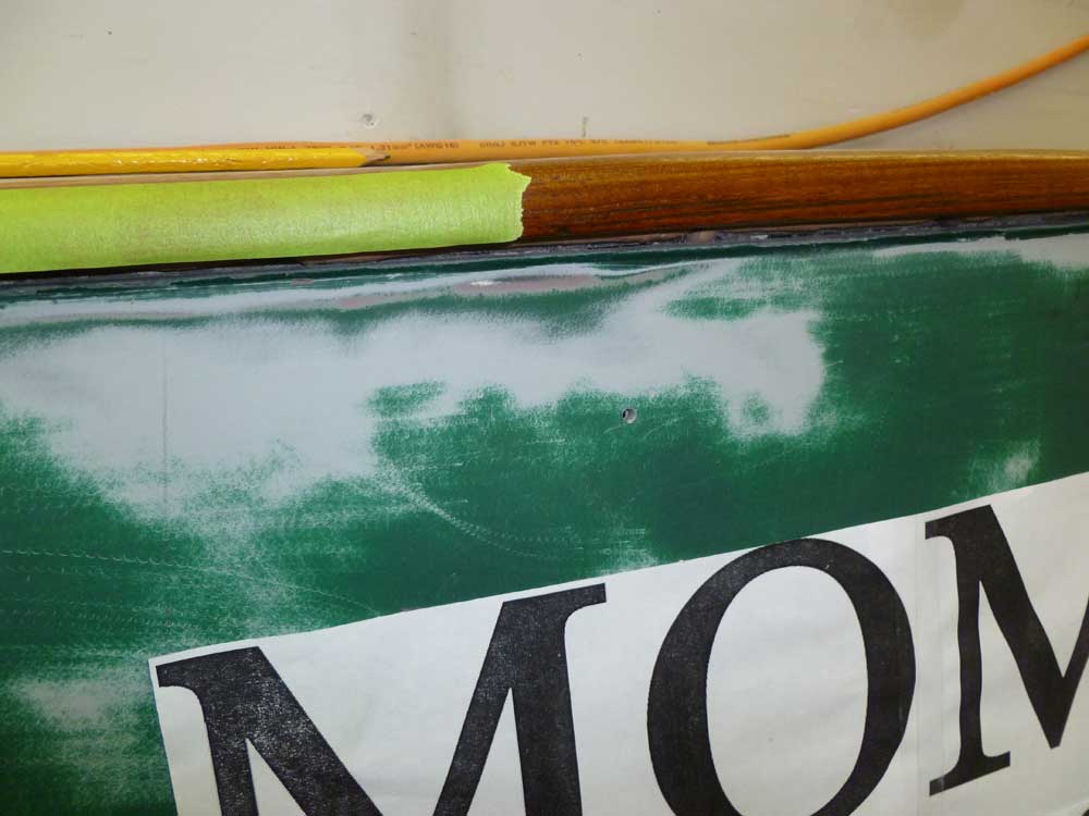
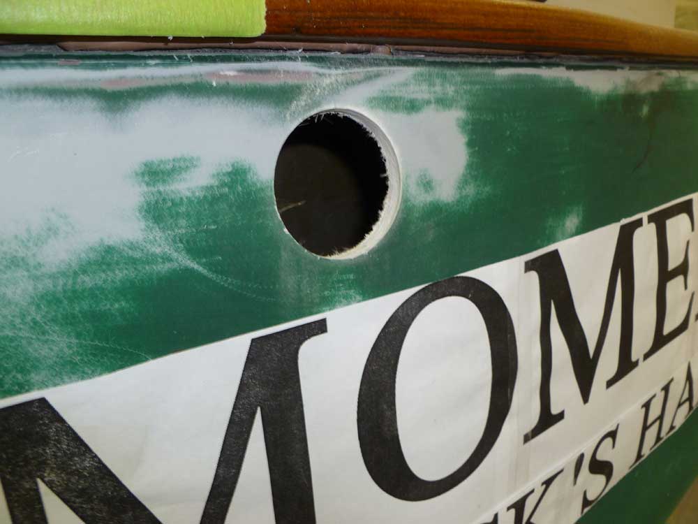
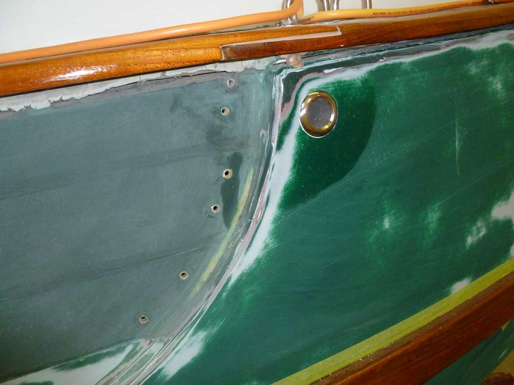
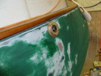
After various considerations, I finalized the fittings'
positions, and from outside drilled small pilot holes so
I could ensure, from inside, that the fittings would run
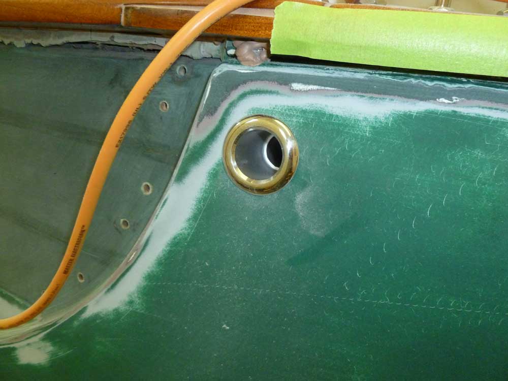
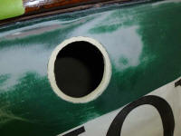
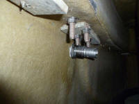
into no obstructions. Satisfied, I drilled a
2-1/4" hole for the exhaust, and a 1-1/4" hole for the
intake, and dry-fit both fittings. |
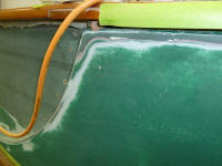


 |
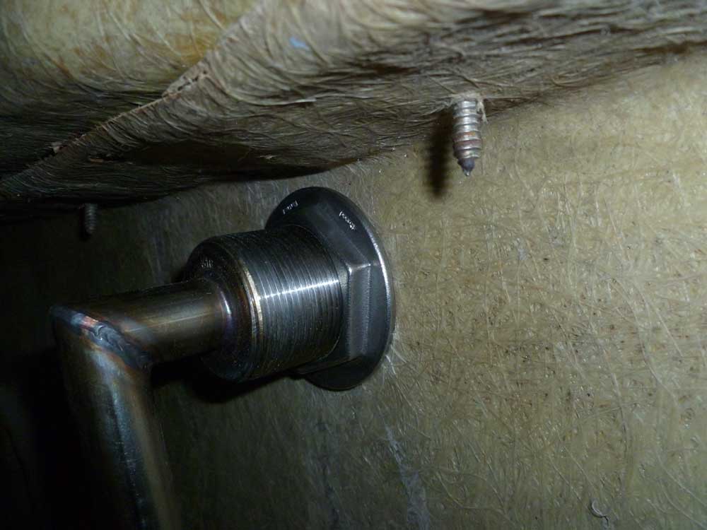
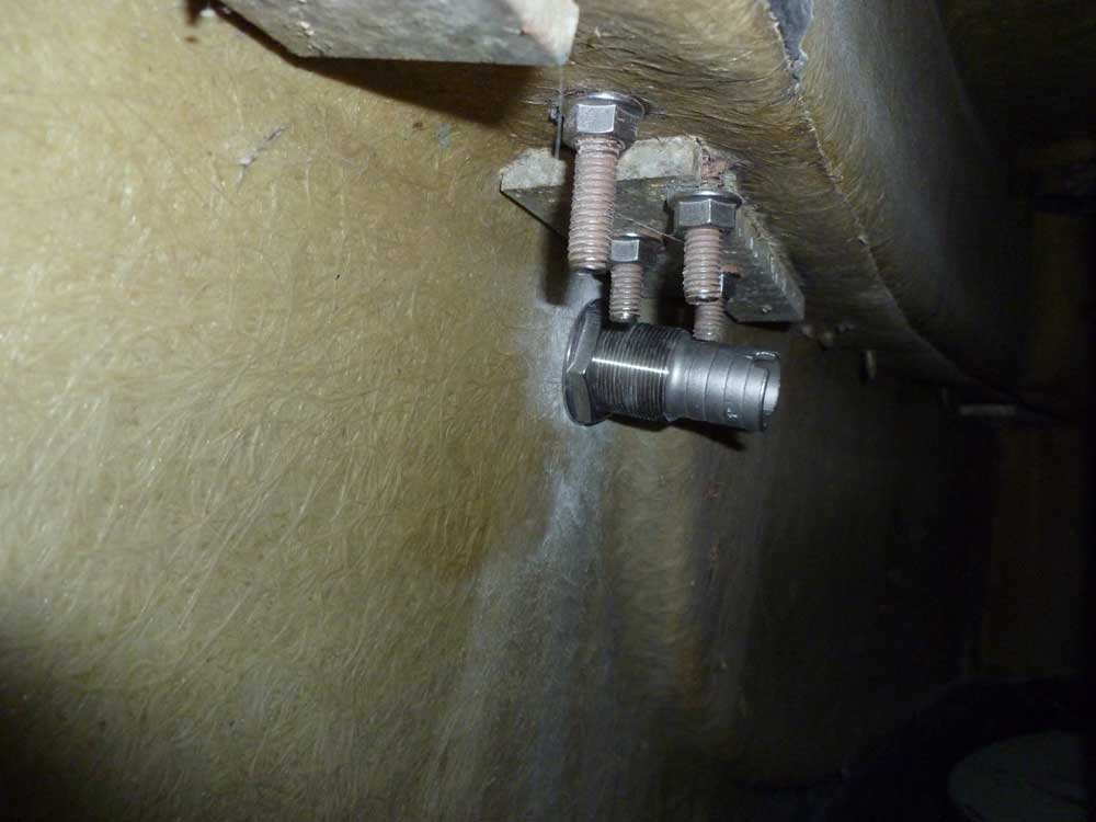
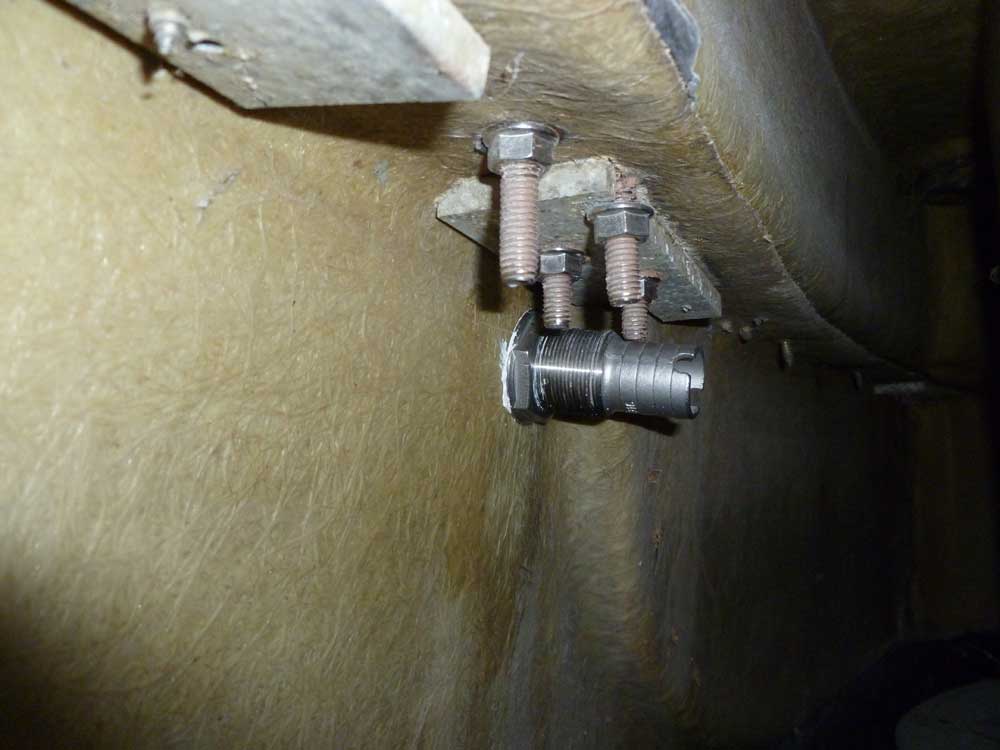
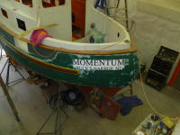
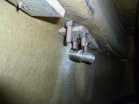
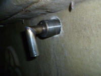
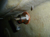
Here it is possible to see how the metal body of the
double-walled exhaust fitting is held clear of the hull
by the spacer. |
 |
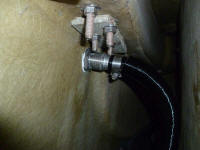
After cleaning up the area and preparing the openings
with masking tape, I installed both fittings, beginning
with the intake. With no special requirements, I
installed this fitting with polysulfide sealant, then
went ahead and installed the intake piping right away,
leaving the heater end's connection for later. |

 |
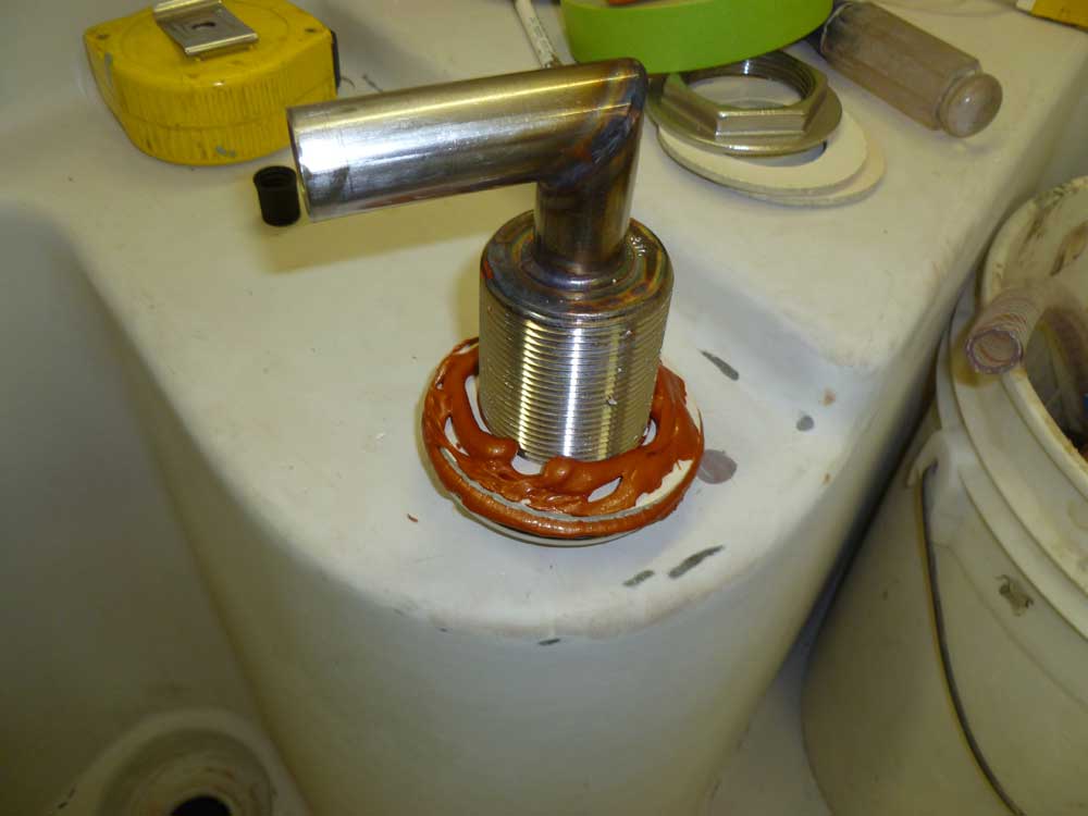
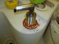
The exhaust fitting required a special high-heat RTV
sealant, Permatex Ultra-Copper. The instructions
called for beads of the sealant on both sides of all the
heat-resistant insulating rings, and I applied some to
the inside of the exhaust flange and caulking groove as
well. I angled the neck of the fitting slightly up from
vertical to provide better access and the straightest
run to the heater down below in the engine room.
I'd work on the exhaust piping later. |
 |
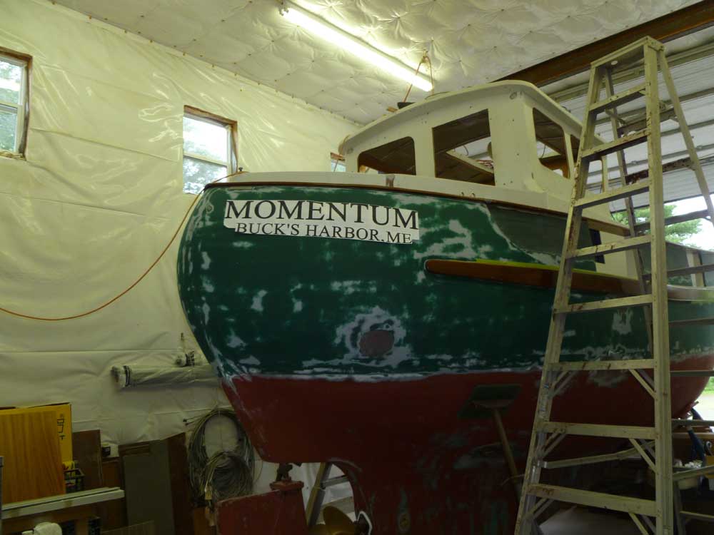
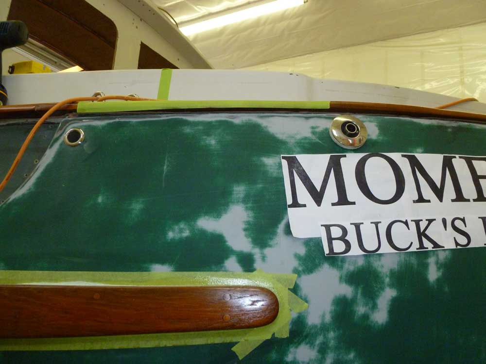
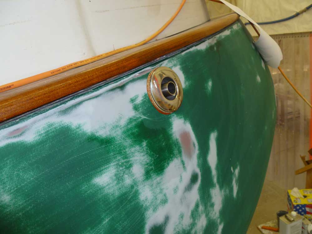
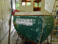
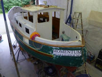
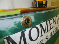
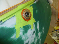
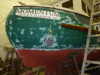
Afterwards, I cleaned up the excess sealant from both
fittings, and reapplied my simulated graphics so I could
continue to observe the appearance and settle on the
final details as needed. |
 |
Normally, I might have waited to install fittings such
as these till after the hull was painted. However,
in this instance, with the hull paint still some time in
the future, I felt that overall progress dictated their
installation now, and I'd simply mask off and paint
around them when the time came.
Similarly, I began to consider the engine exhaust outlet
location. I'd selected 2" stainless steel
fitting from Vetus, and with the fitting on hand it was
time to install it, which would allow me to wrap up the
exhaust hose installation--one of the final engine loose
ends. I planned to have the outlet higher and
farther aft in the hull than the original (which had
been responsible for the boat's sinking under her
previous ownership), which meant exiting from somewhere
in the after steering room. Exactly where remained
to be seen, but from inside and out I considered various
options before taping the removable exhaust flange to
the hull in one proposed location and letting things
settle overnight before continuing. |
 |
| |
Total Time Today: 4.75 hours
|
<
Previous | Next > |
|
|