Project Log: Saturday, February 4, 2012
After last Sunday's problems with my Seastar steering
cylinder and fittings, I contacted the tech support
department at Teleflex, through an individual I'd been
in contact with earlier during my research process.
By afternoon on Monday, he'd responded with a few
questions, then put me in touch with the warranty
department, which was extremely responsive and concerned
about the nature of the problem that I'd had. The
understanding I got from all this was that there'd been
past issues with leakage at the fittings that caused
Teleflex to change how they installed the fittings;
whether or not this was now causing new issues (other
than mine) would remain to be seen.
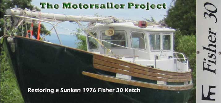
After various email discussions where I related what I'd
done and what had happened, on Wednesday I received a
brand-new cylinder, with the bypass kit already
installed. Certainly I can offer nothing but
praise for how well this situation was handled by
Teleflex. Thank you. I couldn't have hoped
for an easier or more expeditious response to the issue. |
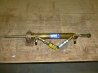 |
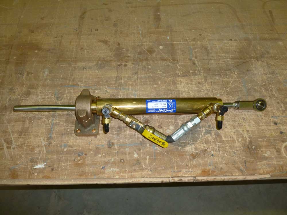
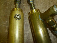
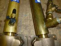
Before I sent the damaged cylinder back as requested, I
compared the two side by side. Perhaps it was just
the different fittings one each, but somehow the holes
and threads on the first cylinder looked different than
on the new one. Maybe not. In any event, the
problem at my end was now solved. |
 |
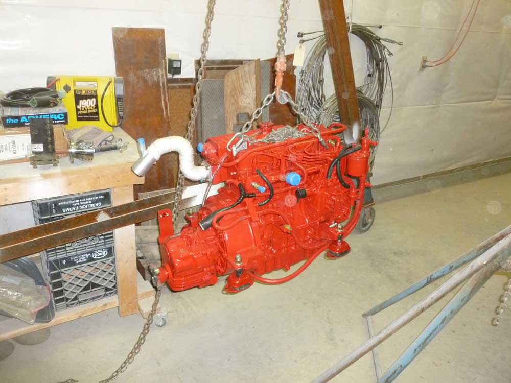
There were a few minor things I wanted to do on the
engine before putting it in the boat. A constant
frustration in working with things is fussy fasteners,
and on this engine I decided to change a few things so
that it'd be more convenient for me later on, both
during later installation/connections steps and for
future maintenance concerns.
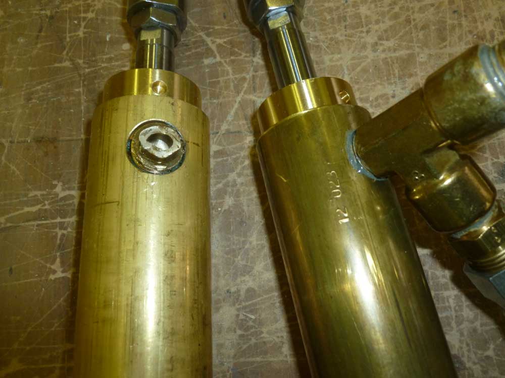
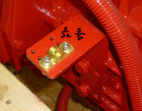
I have always hated the little clamps required to hold
engine control cables in place. These clamps are
comprised of two separate pieces--a base plate and a strap
eye with a special ridge that holds the cable securely.
While the clamps are what they are, and I had to work
with them, I could make some favorable changes to the
stock fasteners, which always seem to be tiny panhead,
slotted screws. Slotted screws are always harder
for me to work with. Plus, I think the stock
fasteners were mild steel.
Working in tight, dark spaces to install cables, these
fasteners--both of which must generally be loosened and
removed in order to clamp the cable in place--coupled
with the two-piece clamp system always seemed to make
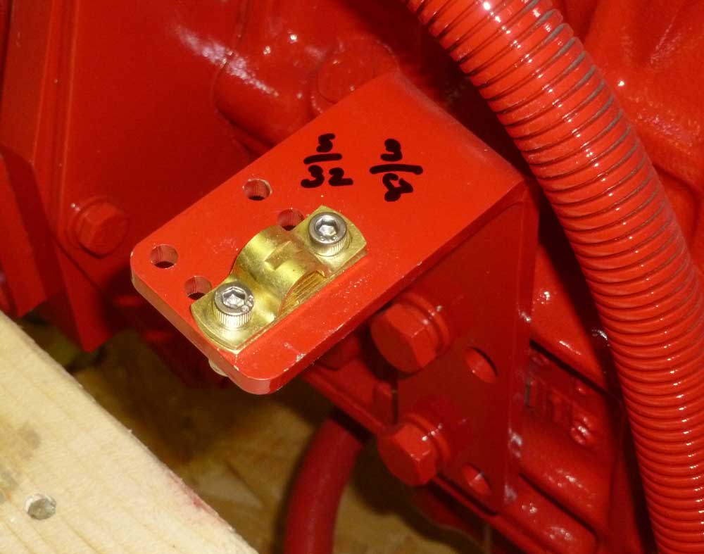
the process harder than it needed to be. To help
make it a little easier to install my cables down the
road, I replaced the standard screws with some stainless
steel socket head screws of similar size, which I hoped
would be easier to use when the time came. I often
mark screw and nut sizes right on a convenient surface,
which makes future maintenance a little simpler. |
 |
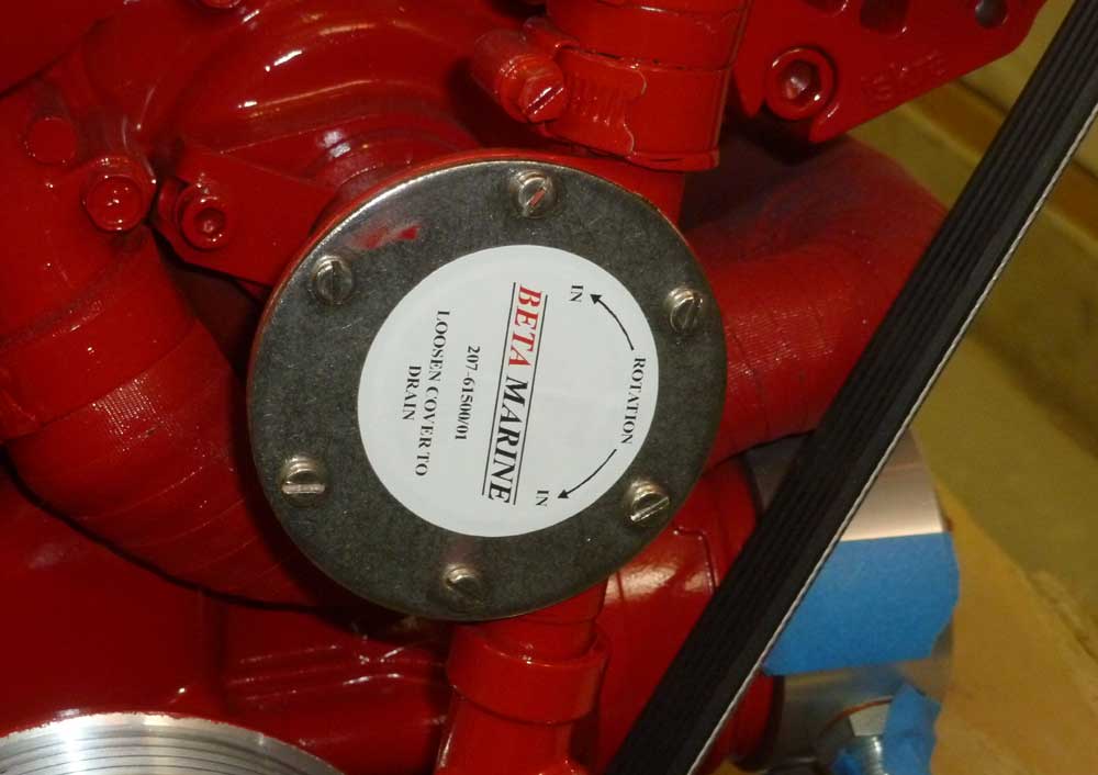
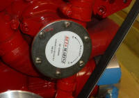
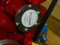
One nice feature of Beta engines is that the raw water
pump is located front and center, not hidden in some
hard-to-reach area. However, the cover plate over
the impeller was secured with six tiny screws (also
slotted), and I felt this could be improved upon.
On my
last boat, which had a small Yanmar diesel with a
backwards-mounted raw water pump, I installed a
Speedseal cover on the housing.
Though I never had to change the impeller under pressure
(I changed it annually as a matter of course), the
Speedseal made it easy and convenient. There were
two features of the Speedseal that I liked: first,
it used a machined groove and an O-ring to seal the
cover, rather than paper gaskets; and second, it used
knurled head fasteners to secure the cover plate.
I would have installed another Speedseal here, but
fortunately this engine used a Johnson raw water pump
that already had an O-ring seal, not paper.
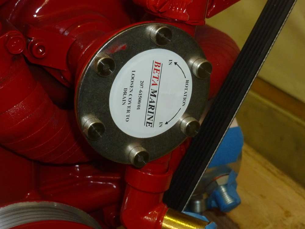
Because access to the pump was so straightforward, I
elected to simply replace the existing screws with new
knurled head fasteners to make removal easier.
Even under controlled, annual-maintenance circumstances,
I'd no patience for dealing with such tiny screws, and I
knew this simple change would make me happier for years
to come.
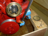
Because I wouldn't be running the engine for some time,
I removed the impeller and stored it elsewhere, so that
the compressed blade didn't become permanently
distorted.
|
 |
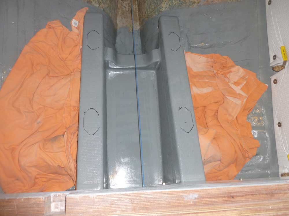
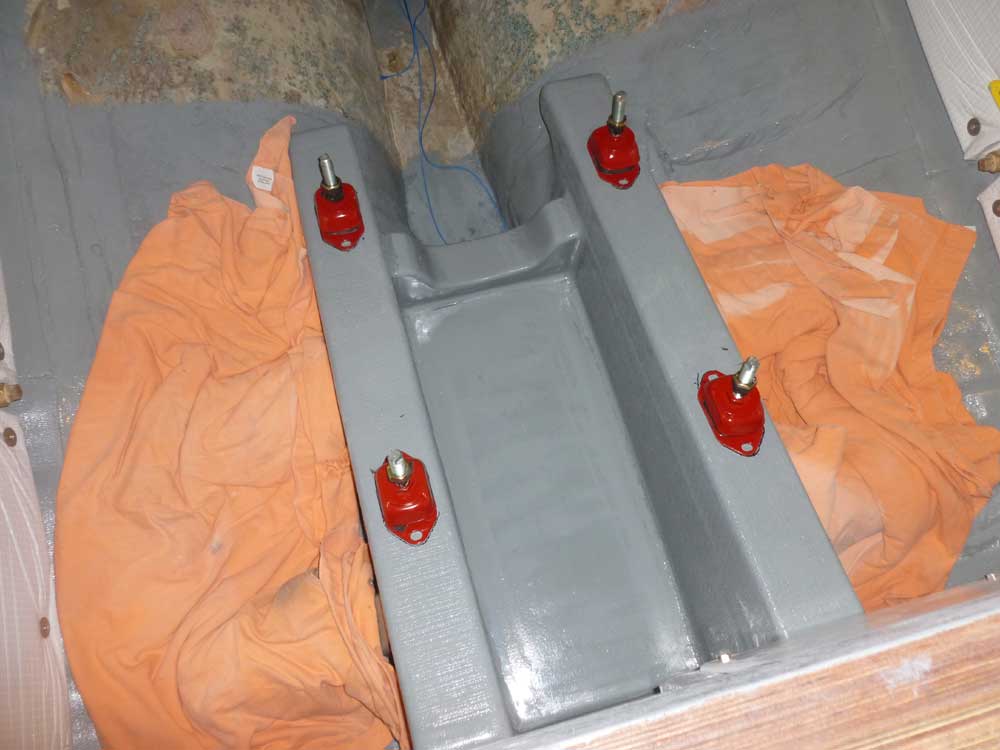
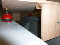
Up in the boat, I set up the centering string one last
time, and, with the flex mounts back on the template,
aligned the template and mounts carefully, ensuring that
the template was in the right position and that the four
mounts were in line with the foundations.
I also determined exactly where I wanted the engine in a
fore-and-aft direction, as I had a little leeway here.
I considered the length of the stuffing box assembly and
propeller couplings, access to the front of the engine
for impeller and belt maintenance, and clearance around
the forward panel in the engine room, among other
things, before settling on the location.
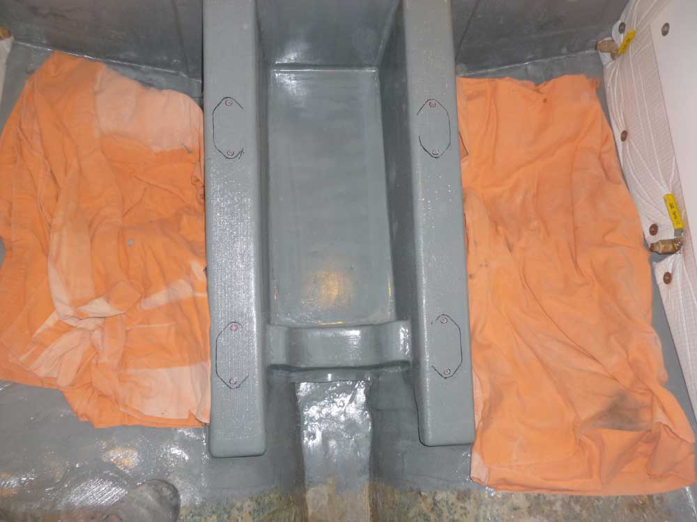
Then, I traced around the mounts' base plates to give me
a reference for their locations. |
 |
Before removing the flex mounts from the template for
good, I used some tape to secure the adjustment nuts in
place, so they wouldn't move during later steps.
This would help ensure that the engine was more or less
correctly adjusted when installed. Then, I placed
the mounts on the foundations, following the traced
outlines, and marked the bolt locations on each. |
 |
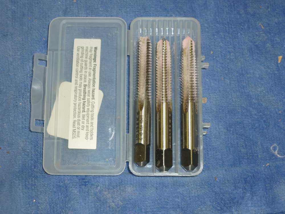
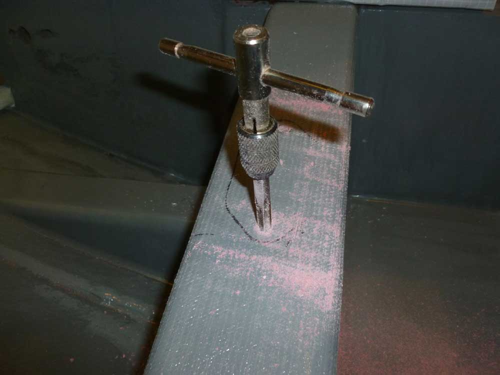
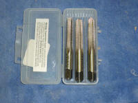
I center-punched each bolt location, keeping them in the
centers of the slots to allow for side-to-side
adjustment if needed, then drilled and tapped each hole
for the 3/8" fasteners I'd use to secure the engine to
the foundations. Because these were blind holes, I
used a series of three taps (taper, plug, and bottoming)
to ensure that the threads extended all the way to the
bottoms of the hole, so that the fasteners wouldn't
bottom out on the threads. I used a hand tap
handle to give me better control. |

 |
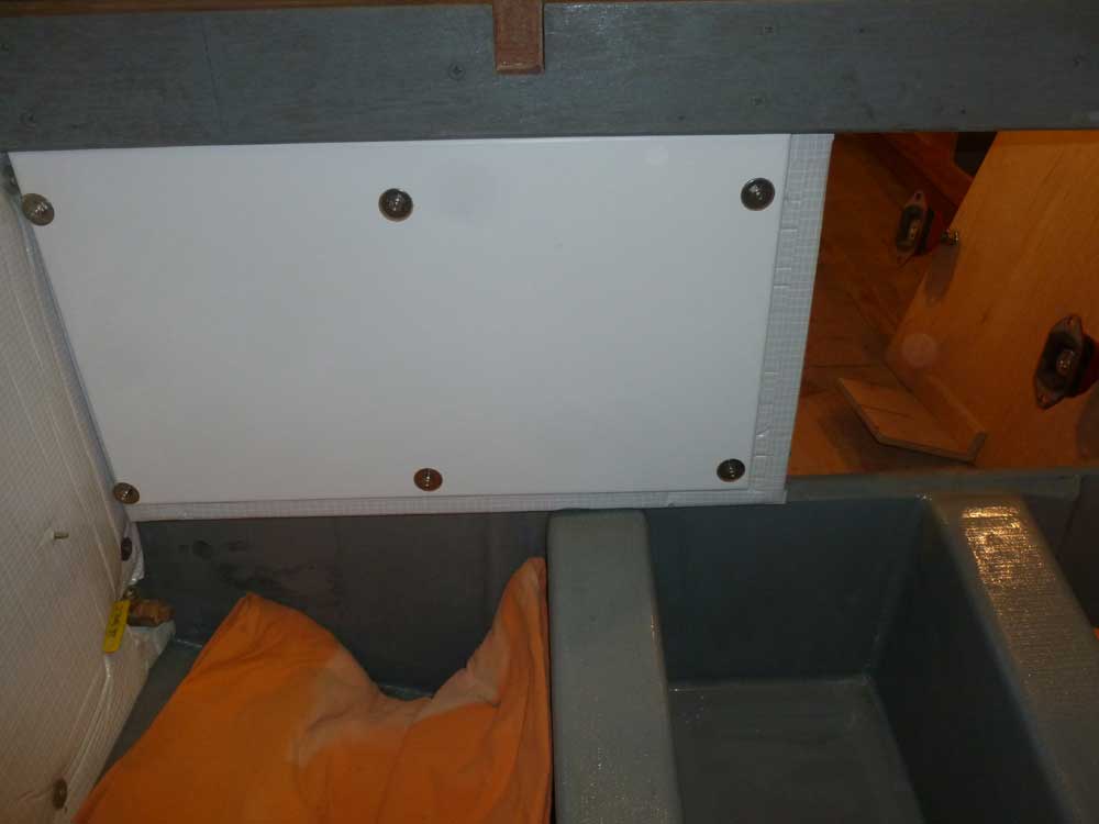
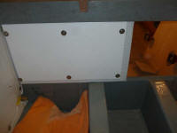
During an earlier test fit of the plywood panels that I
was securing around the engine room perimeter, to cover
the insulation and give me a place to hang various
equipment, I'd discovered that the mounting studs didn't
penetrate as far through the panel as I wanted, meaning
that the nuts wouldn't thread completely on. So on
each of the three panels, I milled a recessed area at
each fastener location so that the washer and nut could
extend a little deeper. Then, I installed the
forward and starboard panels, and the port panel
temporarily, as I'd need t remove it for a couple of the
installations required there. |
 |
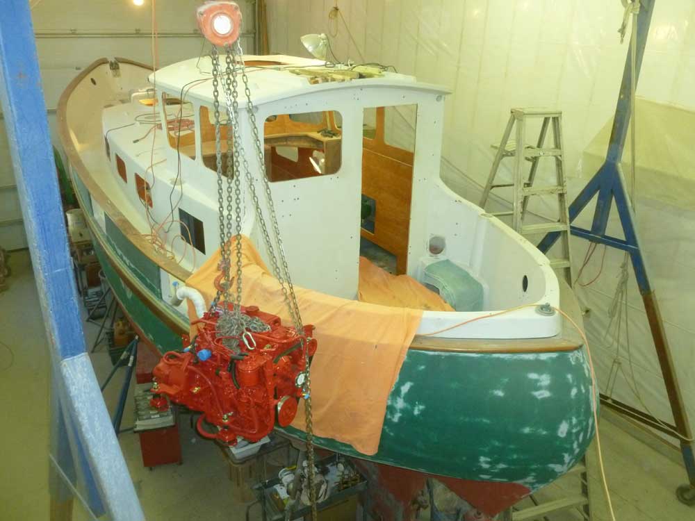
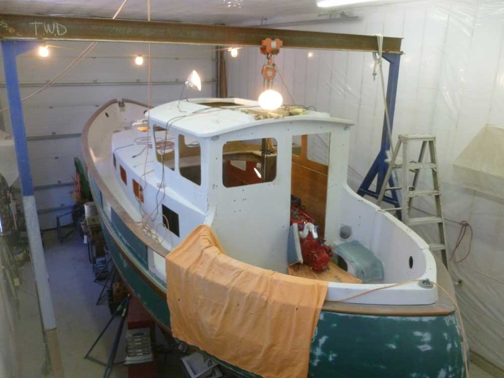
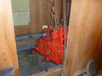
I'd lift the engine into its final position in two
stages, since I didn't have enough overhead clearance to
raise the engine above the pilothouse and its large
overhead hatch: first from the shop floor to the
cockpit, then, after repositioning the hoist, from the
cockpit into the engine room.
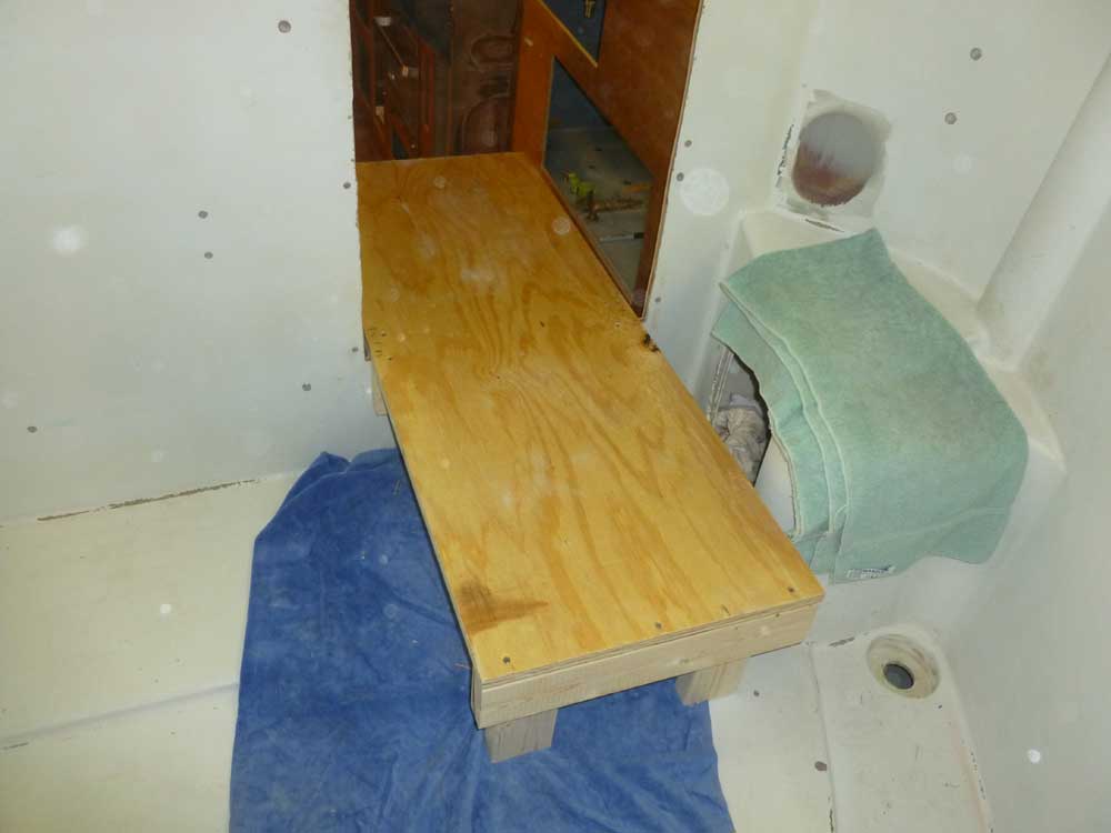
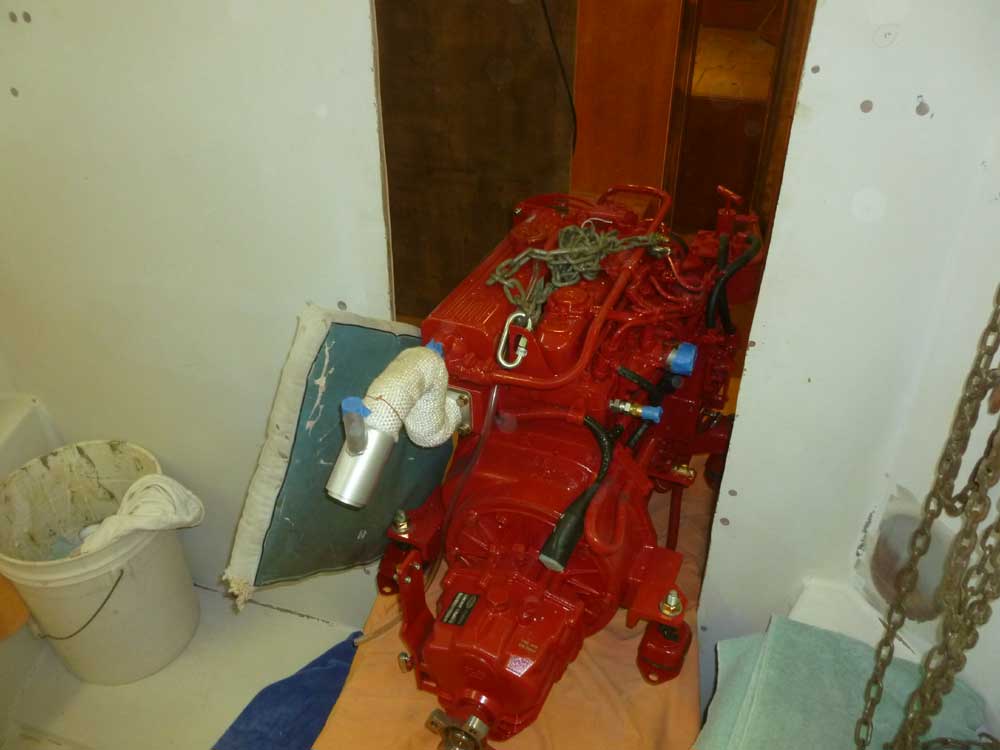
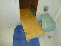
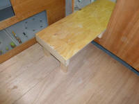
To make the transition between the cockpit and interior,
with the pilothouse door sill well above the surfaces on
each side, I built a simple plywood platform that
spanned between the pilothouse and cockpit. I'd
rest the engine on this platform as I switched the hoist
from one side to the other. |
 |
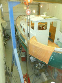
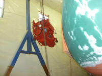
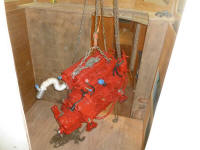
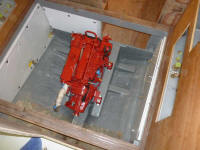
I set up my gantry crane and chain hoist, and lifted the
engine off its shipping crate so I could install the
four flex mounts. Then, I raised the engine into
the cockpit and onto the door platform, which I'd
covered with some sheets. |

 |
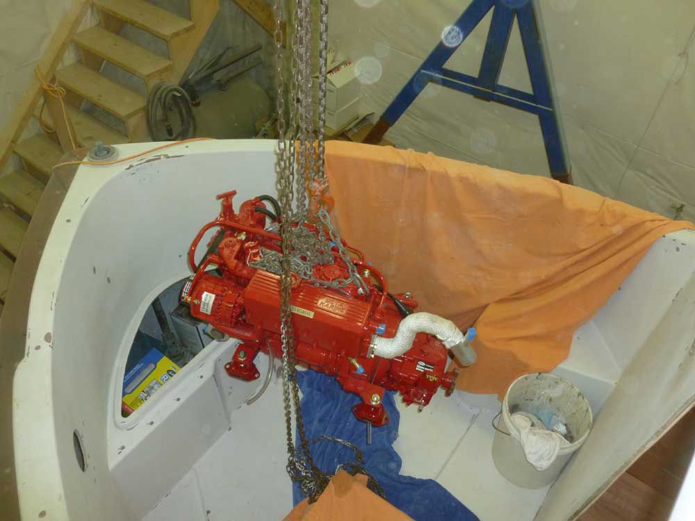
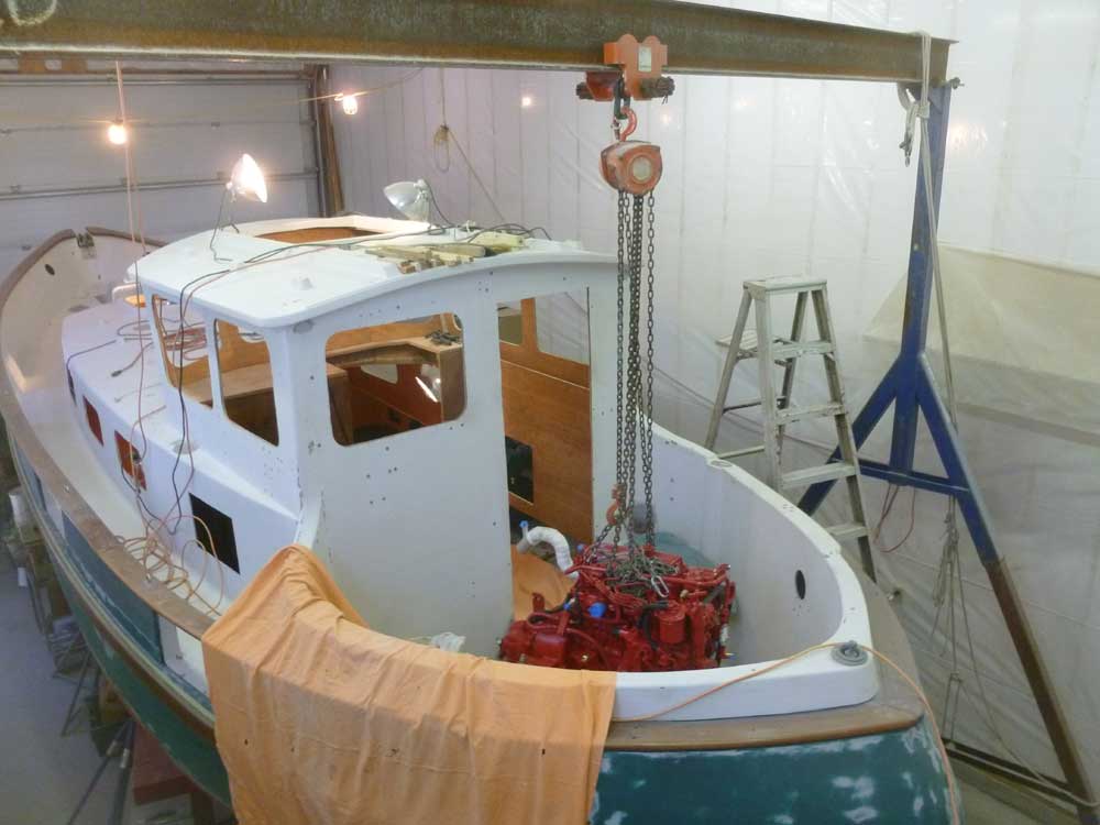
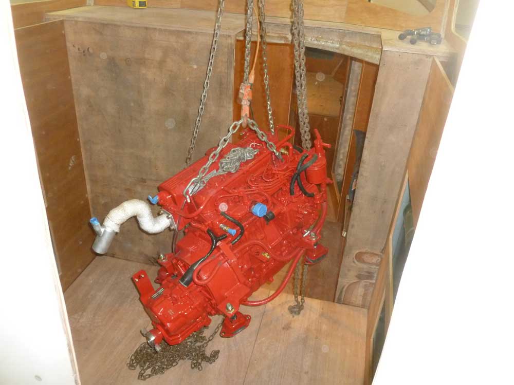
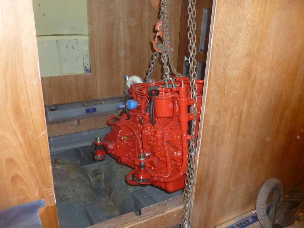
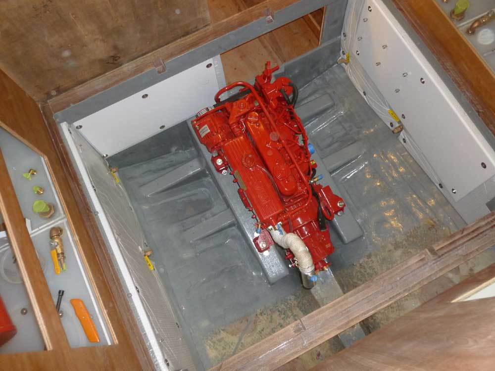
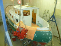
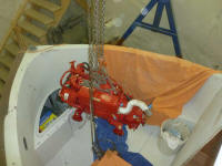
I moved the hoist so it extended through the pilothouse
hatch, then reconnected it to the engine and pulled the
engine the rest of the way into the pilothouse.
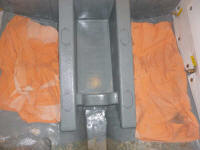
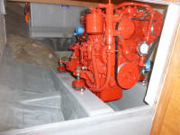
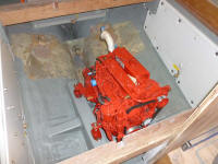
after removing the pilothouse sole and supports, I
lowered the engine into place on the foundations, lining
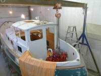
it up with the predrilled holes. With a little
pushing and shoving, and straightening the mounts as
needed, I secured bolts in all of the foundation holes,
then removed the hoist.
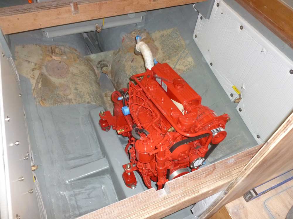
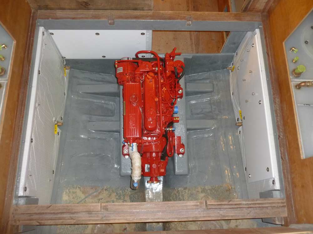
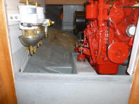
The engine was a great fit in the boat, with plenty of
room on all sides and excellent access to everything.
What a pleasure to have such an expansive engine room
(though additional installations would shrink it over
time). |


 |
As many times as I have put engines in boats, the
anticipation and thrill of having the engine end up in
the proper position, and aligned with the shaft, never
gets old. Despite my careful layout process, I
never take for granted that the engine will fit as
anticipated, so when it does, I continue to be somehow
amazed; it's a palpable thrill.
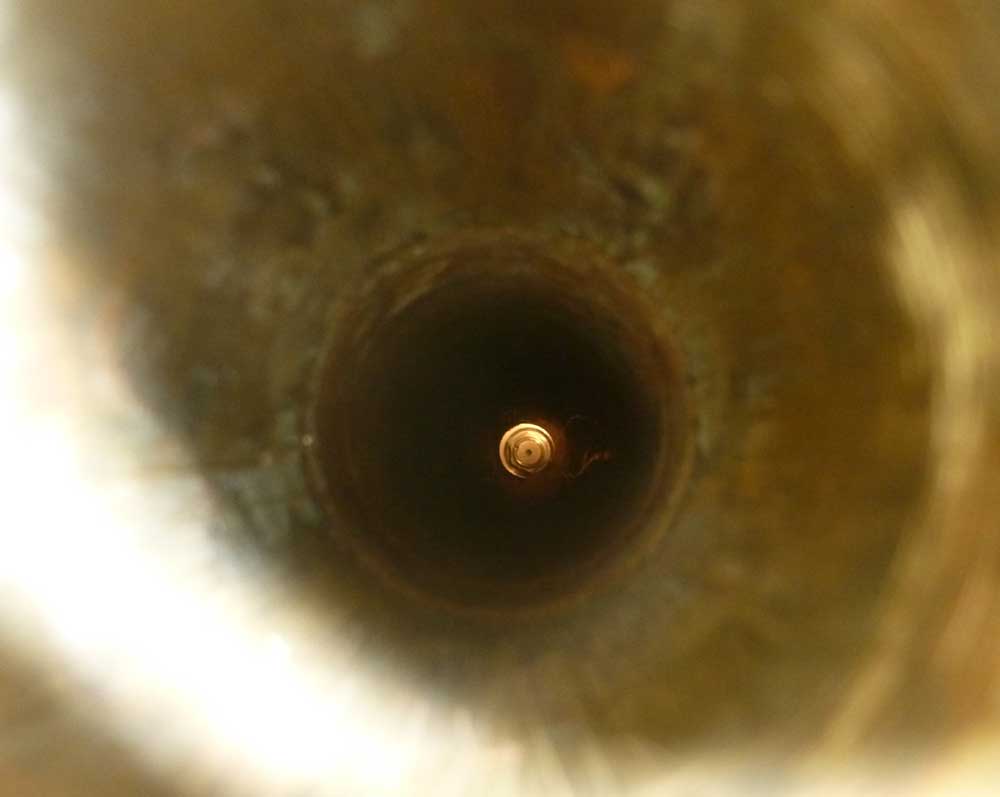
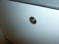
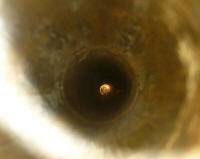
With the engine loosely secured to the foundations, I
peeked in from the outside of the stern tube. If
I'd done my templating, new foundations, and layout
right, I should see the center of the transmission
coupling more or less centered in the tube: it
was. This meant that the engine was generally in
the right position, though final adjustments would have
to be made once it was time to install the propeller
shaft. |
 |
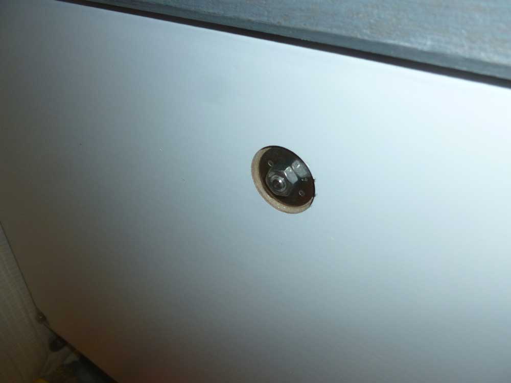
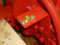
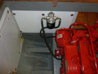
To ensure prime real estate on the adjacent bulkhead
panel, I went ahead and installed the remote oil filter
housing right away, choosing a location near the engine
more or less dictated by the stiff hoses and the angles
at which they needed to attach to the engine end of the
system. Later, I'd secure the hoses against
movement and chafe. |
 |
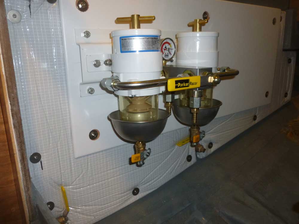
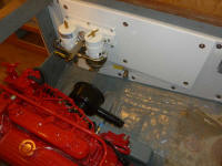
On the starboard panel, I installed the duel Racor fuel
filter setup, which location and bolts I'd laid out long
ago. This filter system allows on-the-fly filter
switching between two identical filters, allowing one to
always have a clean filter ready to go. To make
maintenance on the filters easier, I replaced the
standard drain plugs beneath the bowls with small
valves. |

 |
| |
Total Time Today: 6.75 hours
|
<
Previous |
Next > |
|
|