Project Log: Monday, September 3, 2012
I spent the day on wiring and electronics networking
chores, and finalized a too-lengthy list of needed
cabling and accessories to complete the electronics
networking.
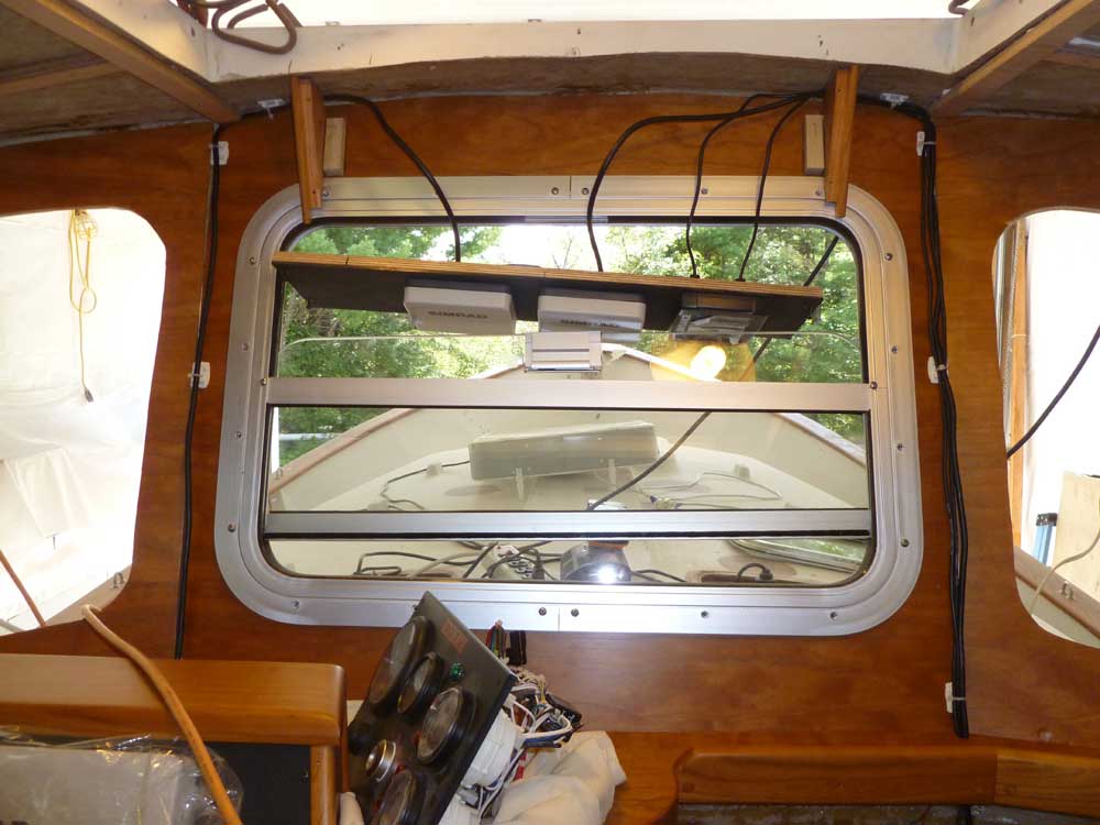
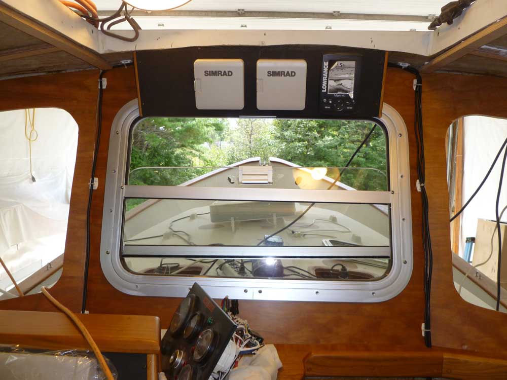
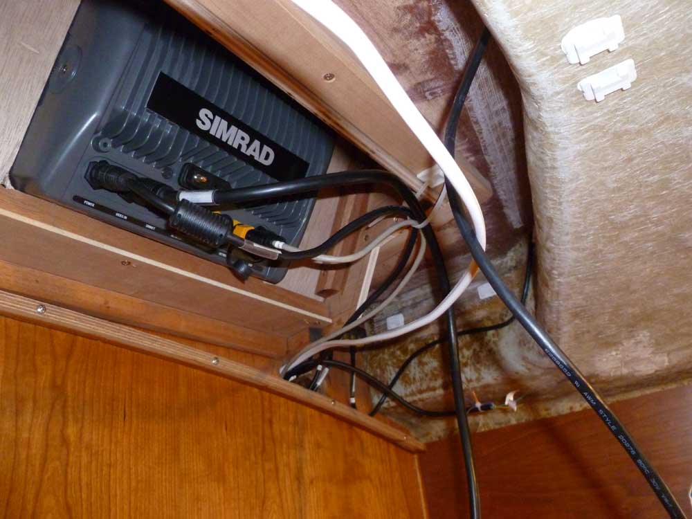
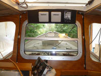
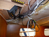
Beginning with the cables I had, I attached the
appropriate cables to the instruments and secondary GPS
in the overhead electronics box, and test-fit it in
place, eventually leading the cables through the dash
and securing them in place along seams in the plywood
paneling where I could mill and install trim later.
I left enough slack in the cables behind the box so that
I could remove either the entire box or the face plate
(as seen here) for access. |

 |
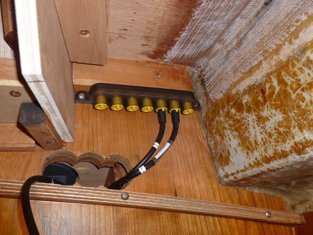
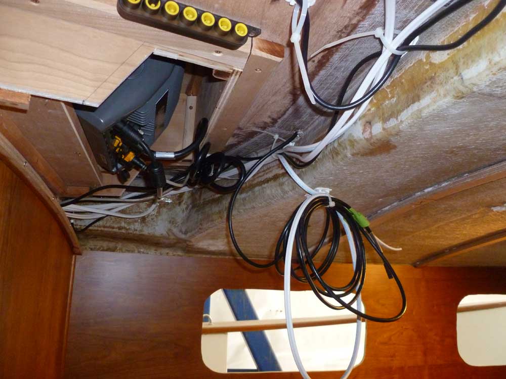
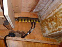
With the beginnings of wiring in place, I chose
locations for two 7-position joiners for the SimNet
system and installed them, then connected various cables
as I went. For future convenience, I numbered the
cables near the connection so I could easily identify
them in the future. I quickly ran out of available
cables, but was able to connect the overhead instruments
and autopilot, along with the GPS antenna and a required
power supply cord for the system. (You'll see more
of this cabling and the other joiner in photos further
down the page). |
 |
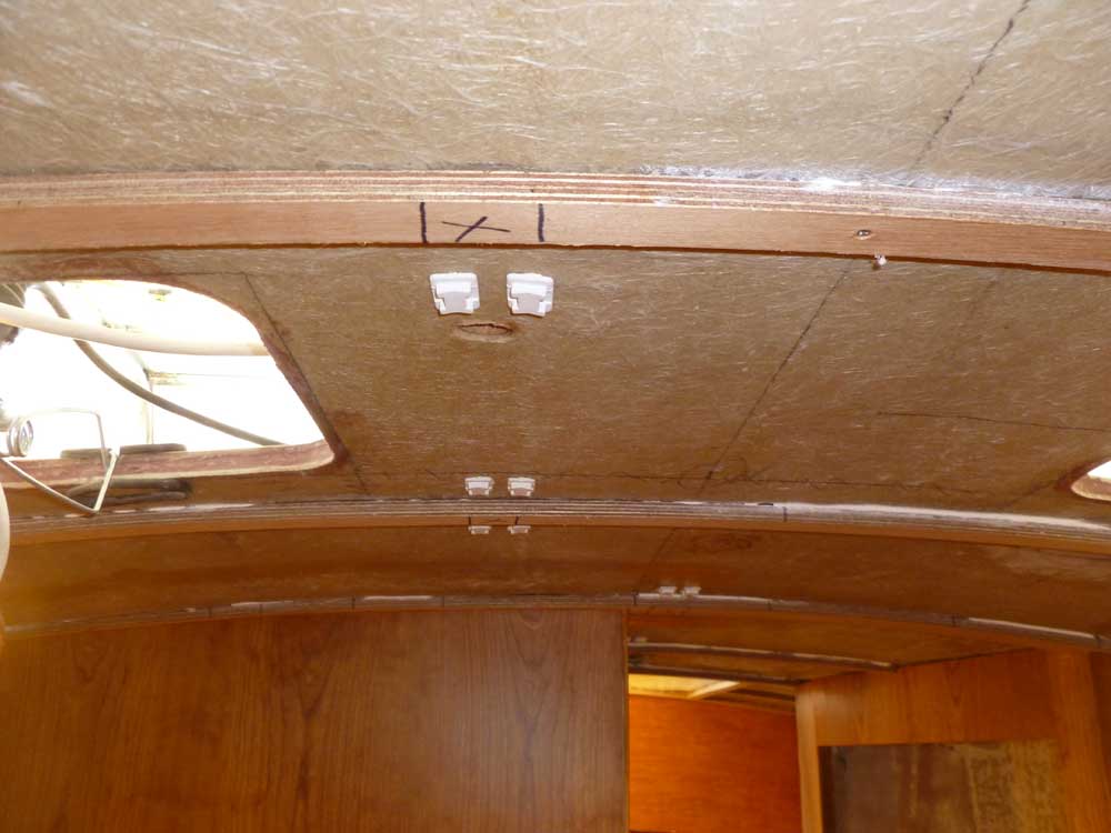
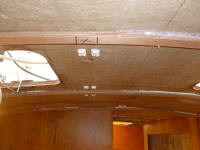
The masthead wind instruments included a special SimNet
cable long enough to run down the mast and all the way
to these connections, but since the mast would need to
be unstepped and these connections broken, I planned
ahead for a junction near the mast step, where I could
easily connect and disconnect not only the wind
instruments but also the mast light wiring. To
this end, I installed cable clamps on the overhead
leading forward, as this route made the most sense and
was most direct. I'd have to cut out small
portions of the overhead cleats to allow the wires to
pass, so for now I left a couple bundles of wire hanging
nearby, for eventual connection to the mast area.
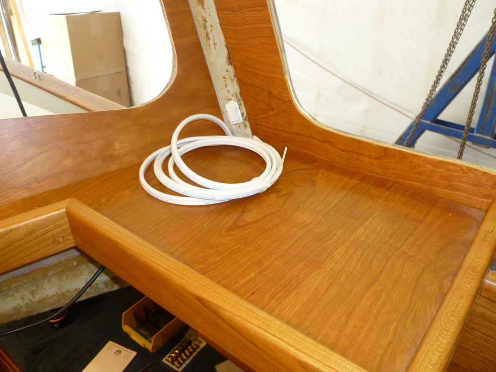
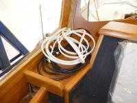
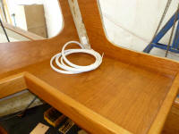
The early stages of bulk wiring tend to leave loops of
cable and excess wire all over. |
 |
Something that slipped through the cracks during the
specification of the electronics system was the eventual
connection of the depth transducer to the system.
Try as I might, I couldn't seem locate a cabling adapter
between the transducer and the available ports in the
plotter unit or SimNet network, other than a separate
sounder module designed for this purpose.
The transducer had been spec'd to mate with my system,
and included the correct Lowrance/Simrad connector end,
but there was no way to connect it directly or adapt it
that I could see. So for a while it looked like I had no
choice but to purchase the BSM-1 sounder module in order
to connect my depth transducer to the system.
More research later revealed that I might have been
looking for the wrong things to adapt. I
later found a Lowrance 127-05 adapter cable that looked
like it would convert between the blue 7-pin transducer
cable and a NMEA 2000 network cable connector (red, in
Lowrance nomenclature), which in turn I could connect to
SimNet through a NMEA 2000 - Simnet adapter cable that I
already had on hand. So I thought I'd order that
cable adapter, which was far less expensive than the
sounder module that I didn't really need or want.
In addition, I'd require several various lengths of the
SimNet cable to complete the connections. I
thought I'd need another length of Ethernet cable to
connect the sounder, but for now, at least, it looked
like I could avoid the sounder module, assuming the
adapter cable above worked as I hoped.
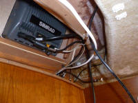
I
ran a 15m length of the Ethernet cable (which is how
this system communicates with certain components, like
the Broadband radar and sounder) through the console and
towards the aft end of the engine room, where I'd
eventually mount the radar control box (since the radome
would be located on the mizzenmast).
|
 |
Meanwhile, I installed several raw lengths of 14AWG
duplex safety wire, my bulk wire of choice for most of
the installations. Because of the various wire
routes I was beginning in the under-dash area, it made
sense to run cables for the running lights (to be
located on top of the pilothouse), an overhead lighting
circuit for the main saloon (though I'd not yet
determined whether or not I'd actually be using overhead
lights at all), and another circuit slated for the
pilothouse overhead lighting. In addition, I ran
wire and connected it to several power leads from the
electronics, including the secondary GPS. |
 |
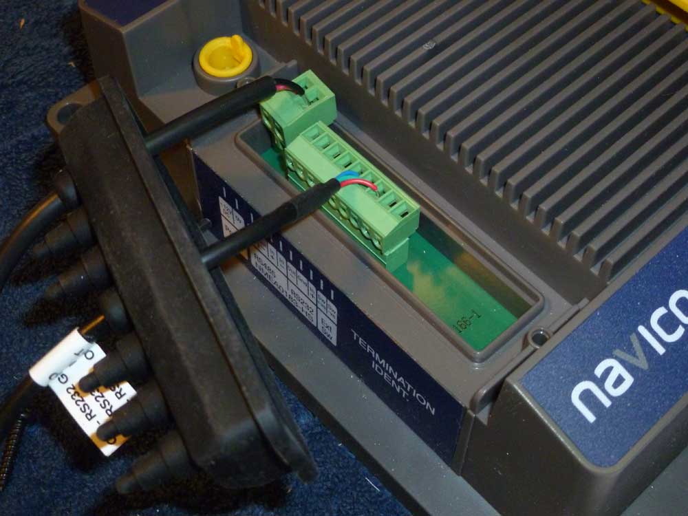
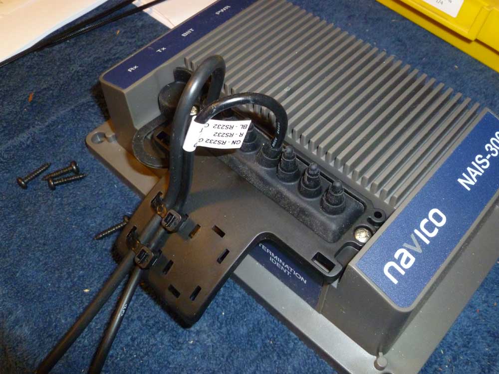
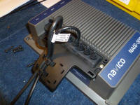
I also wired and installed the AIS transponder.
The wiring included a power supply, plus three wires
required for the included serial connector needed to
connect to a computer for initial setup and registration
of the system. At first I'd had trouble
deciphering the wiring instructions in the manual, but
found that the task was simple and straightforward when
I got into it. Why this modern system relied on an
obsolete serial connector was a question for greater
minds than mind, but having determined this
incompatibility months ago, I was prepared to eventually
connect the AIS to my computer with a serial to USB
converter.
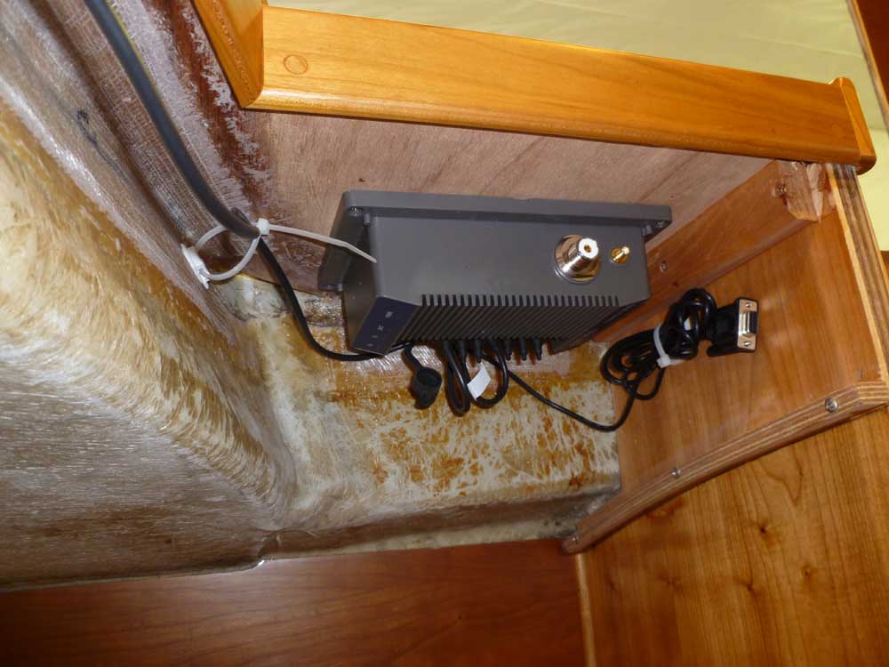
I chose to mount the AIS beneath the starboard side of
the dash, a convenient location for networking and also
to run the separate GPS and VHF cabling up and out of
the pilothouse through the starboard corner trim.
(The main GPS antenna cable would similarly run up the
port side.) This area, and the rest of the
under-dash utility space, would be hidden later by the
overhead and additional trim around the companionway. |

 |
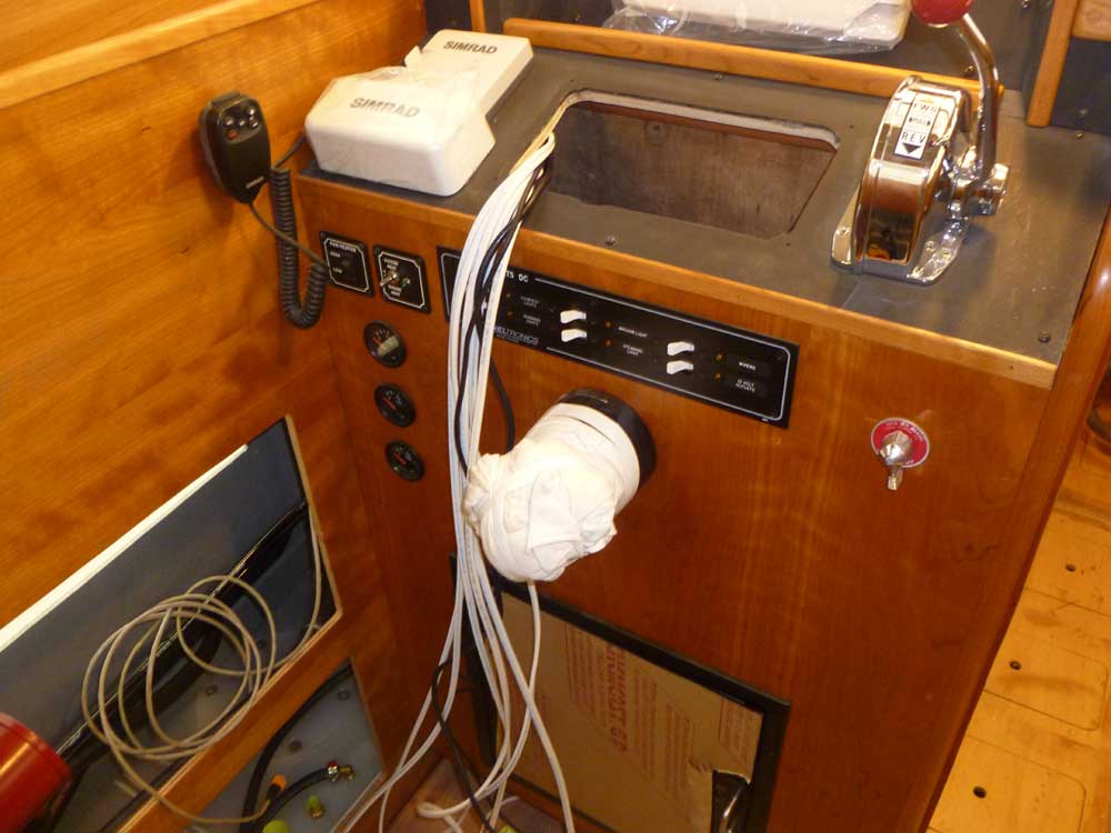
This process left a raw bundle of wires leading into the
console. I'd have to run these down to the lower
section for connection, but for the moment it was easier
to keep them out of the way and led through the engine
instrument panel hole in the console, till I was ready
to determine their route. I left other raw cable
ends bundled here and there as required, pending their
final routing elsewhere. |

 |
I'd order the new SimNet cables and other things
required, and hopefully be ready to continue the process
next time and wrap up this particular segment of the
boat's wiring.
|
Total Time Today: 6.25 hours
|
<
Previous | Next > |
|
|