Project Log: Friday, June 5, 2015
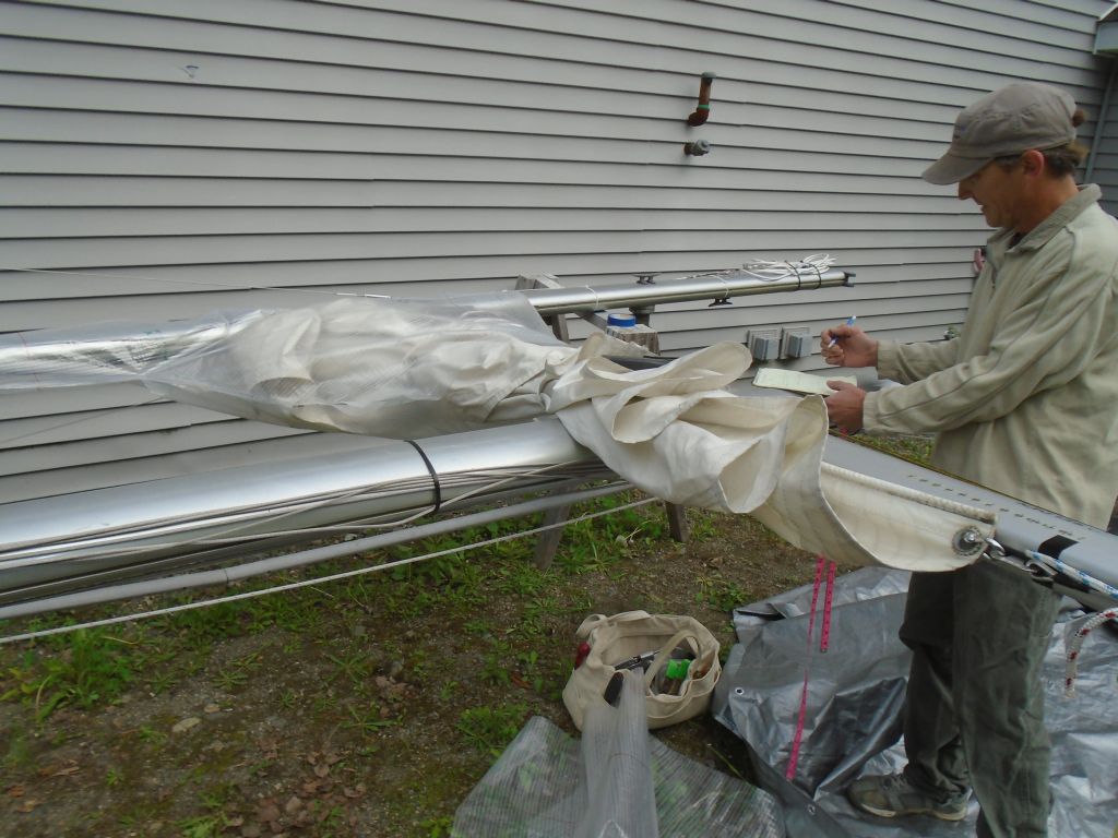
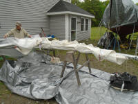
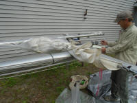
One of the final details not yet dealt with was new
sailcovers for both main and mizzen. To this end,
Jason, my upholstery and canvas contractor, and I agreed
to meet in the morning and mock up the booms and sails
so he could pattern the sailcovers and have them ready
in time for launching.
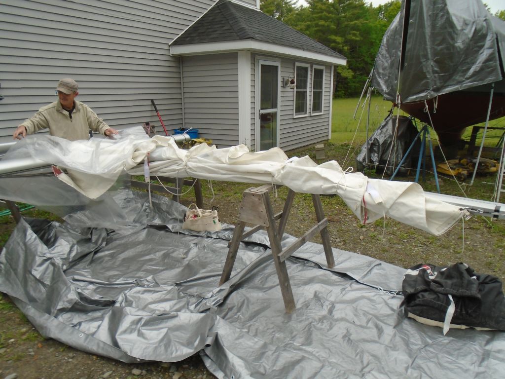
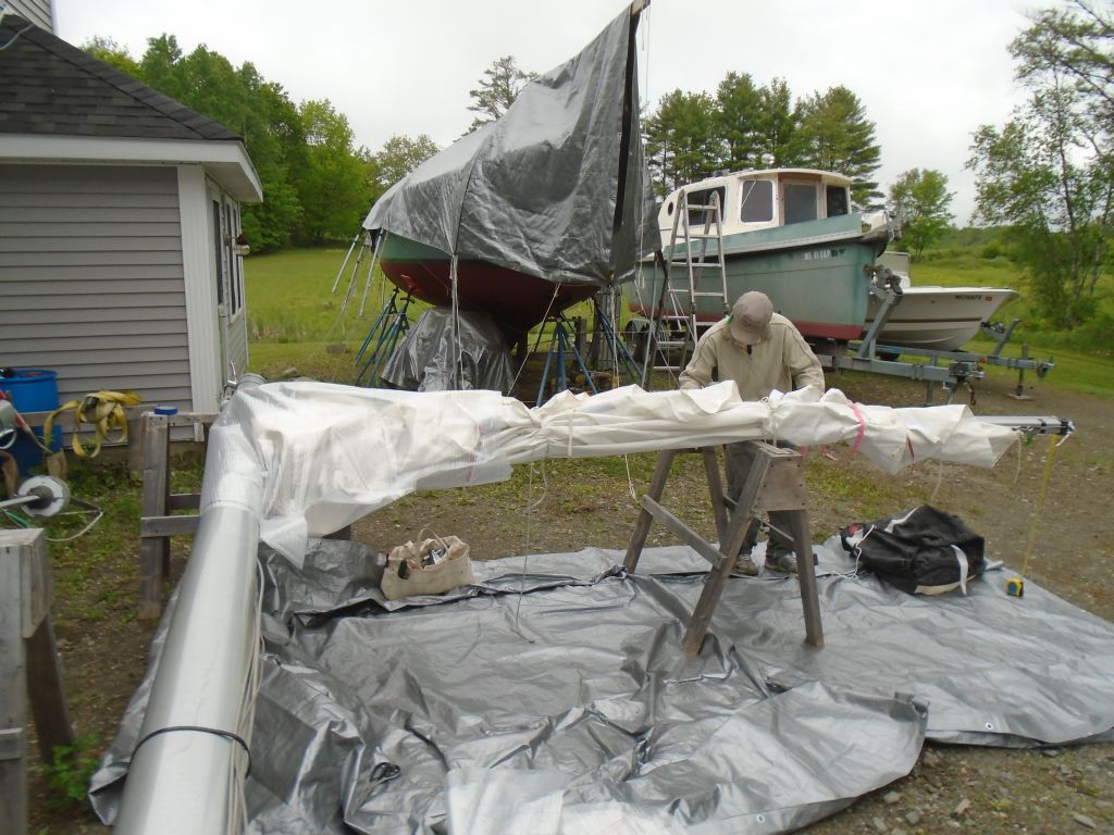
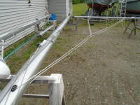
With the masts already set up on sawhorses, it was
pretty straightforward to attach the booms--one mast at
a time--and bend on the sails in a rough approximation
of their eventual stored state, from which Jason could
get the basic measurements and pattern information he
needed.
|

 |
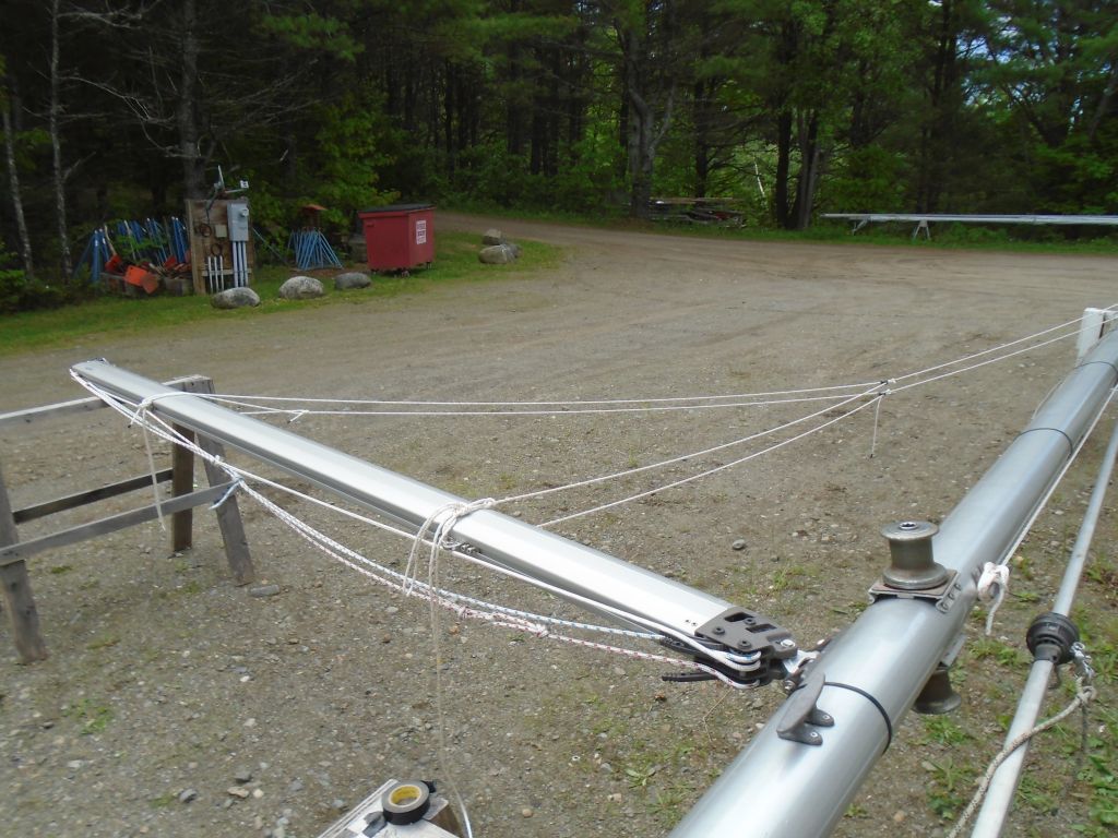
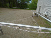
Afterwards, with the main boom still in place, I did one
final preparatory step for the new lazy jacks,
approximating the positions for two legs to the boom and
cutting oversized lengths of line to run to the main
control lines above. I left these lines long and
awaited mast stepping and having the sail in place
before attempting to finalize the boom locations for the
legs. It looked like two legs would be enough, but
it'd be simple enough to split one (or both) into a pair
if needed. The main point of this exercise was to
locate and install the block at the end of the upper
control line, which location I determined by the whim of
my eye and the necessity to have the whole system be
retractable when not in use. |

 |
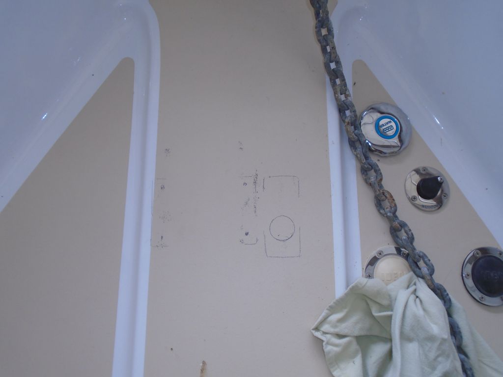
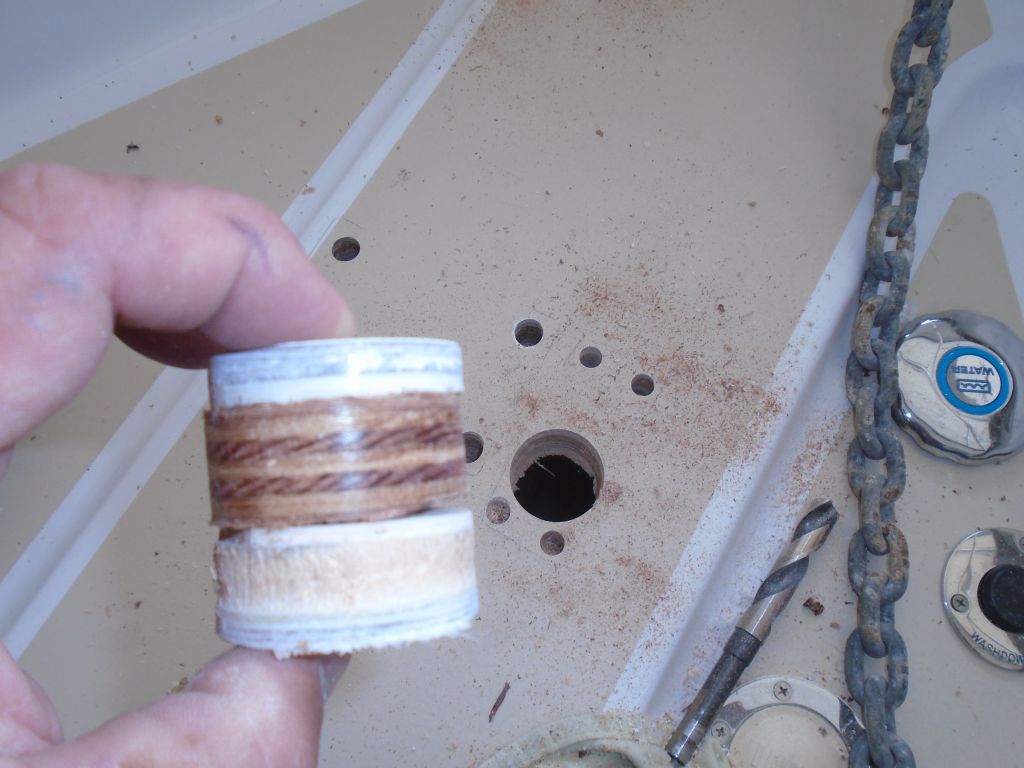
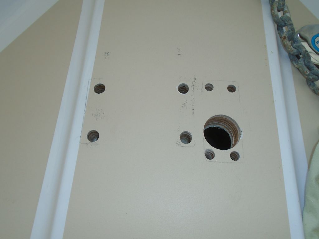
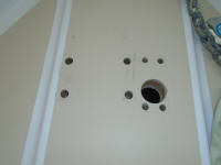
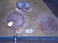
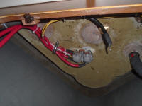
Back on windlass duty a little later on, I started on
the foredeck, where I overbored all the mounting hole
locations for the windlass and chain stripper with large
bits to remove coring from these areas and prepare the
holes for epoxy filling. I also drilled the large
hole for the chain through the deck. |

 |
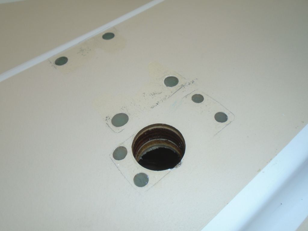
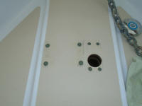
Afterwards, I filled the holes with a thickened epoxy
mixture, and sealed the exposed core edges in the larger
hole. |
 |
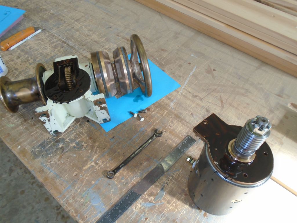
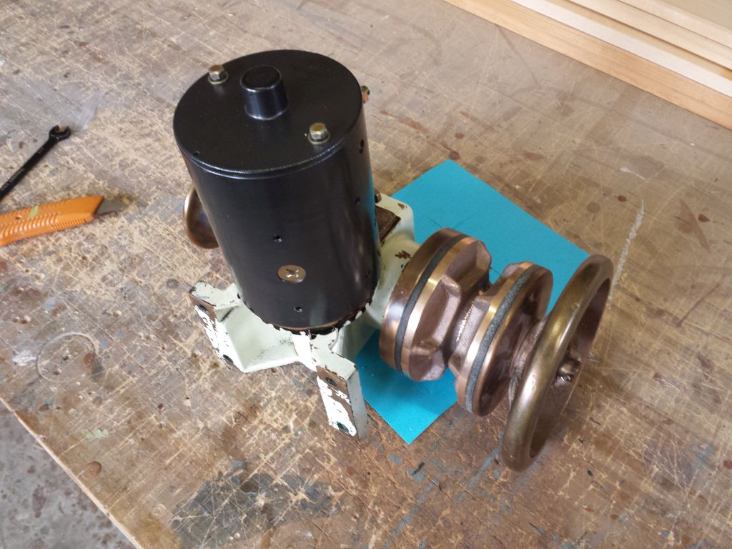
After lugging the windlass on deck the other day--being
all bronze, that thing is inordinately heavy--I'd left
it in place for a time. To my disappointment, I
later discovered some of the windlass oil running down
the deck, suggesting that the gasket material I'd
applied when I installed the motor hadn't "taken"
properly. This left me no alternative but to
remove the windlass back to the bench and reseal the
motor. Apparently, I'd not allowed the liquid
material the required few minutes of air-cure time
before assembling the parts before, so I made sure to do
so now. After assembly, I left the windlass tipped
on end so that the oil in the reservoir would stay clear
of the flange area to give the liquid gasket plenty of
time to cure and make itself right this time. |

 |
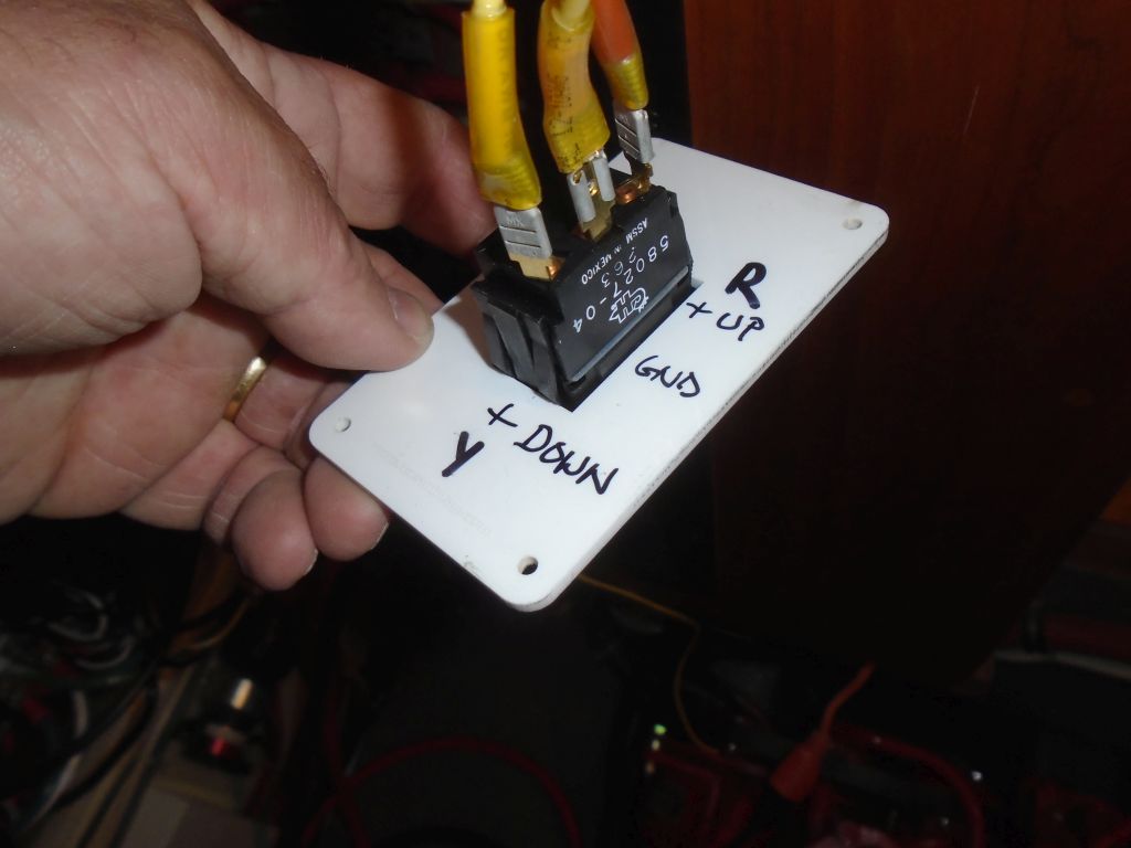
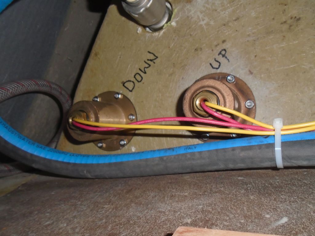
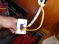
At the helm, I chose a location for a remote switch for
the windlass, and cut an opening for the switch body.
During the cable run for the windlass, I'd led a
two-conductor cable (red and yellow) from the
chainlocker for this purpose (the other end would
connect to the appropriate terminals on the windlass
solenoid up in the chainlocker, which I'd install next).
While both wires of this cable were positive in
function, I chose to overlook the cable color problem,
but marked the switch and cable clearly as to the wires'
functions. The third terminal on the switch
was a ground wire, which I led in to the console and to
one of the negative distribution busses. |
 |
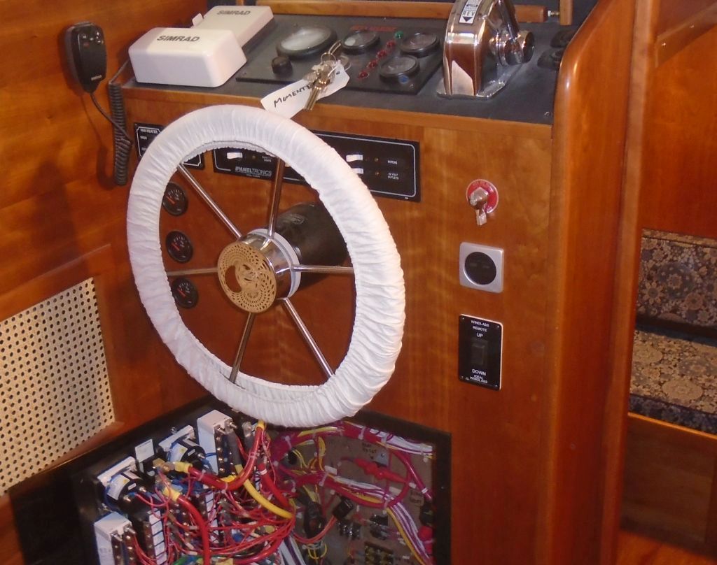
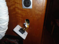
With the switch wiring complete, I installed the panel
in the console, bundling and securing the wires as much
as possible but leaving enough excess to easily remove
the switch for servicing. |
 |
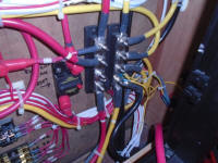
I was still awaiting the main breaker panel for the
windlass, which incorporated a 150-amp breaker, so I
couldn't complete the positive cable runs till that
arrived. However, I could--and did--make up the
negative main cable end, securing it to the negative
distribution buss. It's the large black cable on
the lowest stud. |
 |
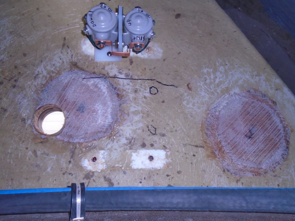
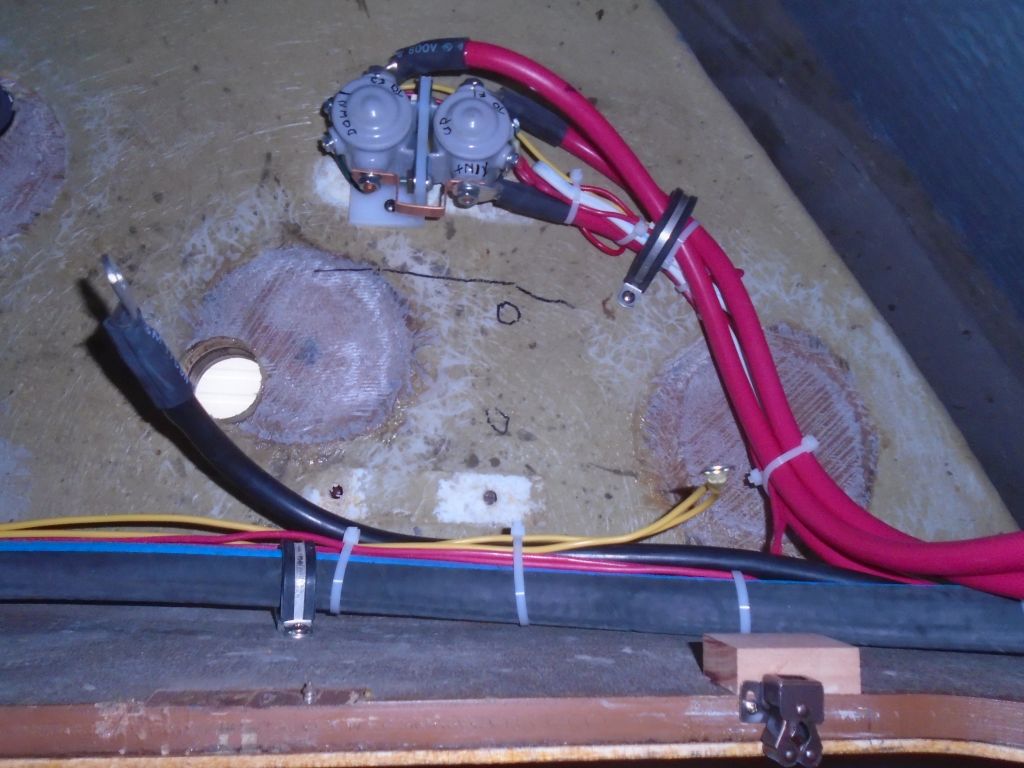
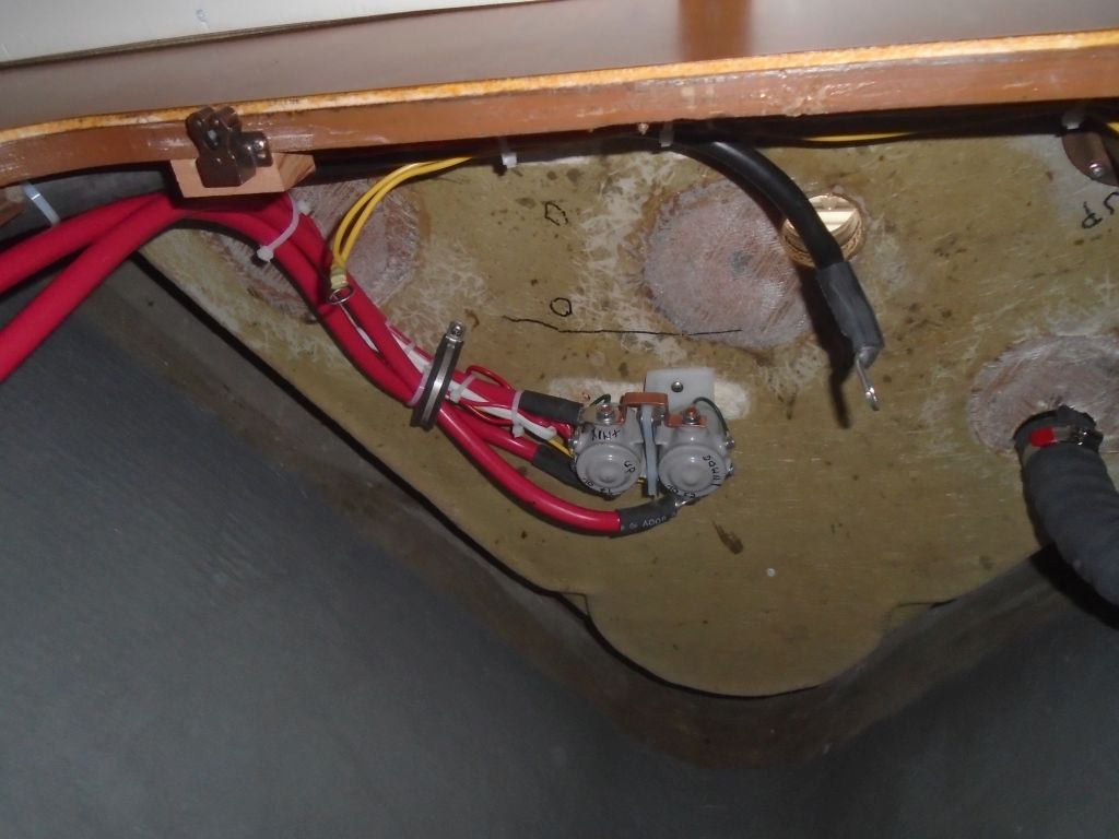
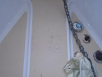
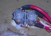
Moving my wiring operation to the chainlocker, I began
by choosing a mounting location for the solenoid unit.
Eventually, I decided the underside of the deck was best
for many reasons, chief among them ease of access and
protection from damage. I made sure to mount it
well clear of the bolt holes and backing plate for the
windlass installation (marked roughly in black marker).
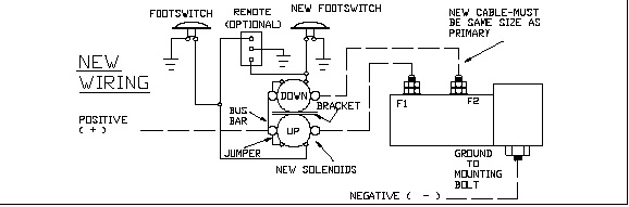
Before mounting, I'd marked various terminals on the
solenoid (as determined by the wiring diagram) for ease
of reference during wiring and later. |
 |
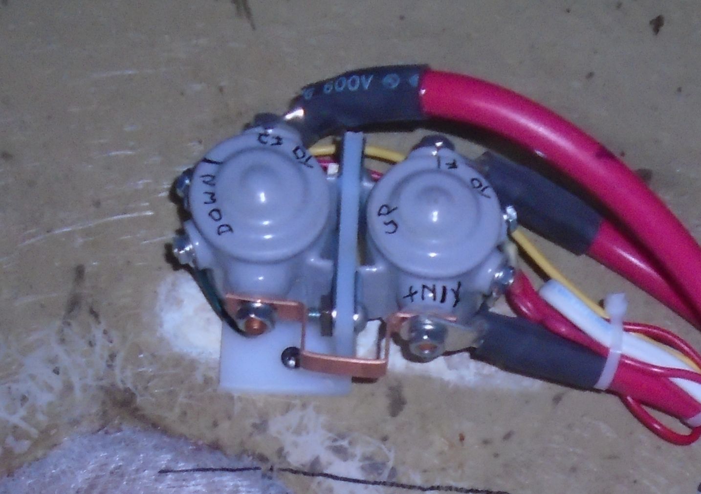
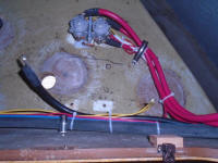
The main positive and negative cables were already led
into the space, along with the two-conductor wire
leading to that helm switch. In addition, I'd
pre-wired the two foot switches in the foredeck when I
installed them some time earlier. Now, I made up
the ends of these wires and connected them as required:
positive leads from the two foot switches and helm
switch to the up and down terminals on the solenoid,
respectively; positive main cable to one of the large
studs on the solenoid; and the negative leads from the
two foot switches, plus the main negative cable, which
for the moment I left dangling as these would eventually
be grounded to one of the windlass mounting bolts when
it was installed.
In addition, I also made up two shorter 1/0 cables that
would lead from the up and down sides of the solenoid
(at the forward [upper] side of the unit) to the studs
on the windlass motor on deck, but I left these hanging
in the space pending final installation a little later
on. |

 |
This wrapped up everything I could do until [a] I
installed the windlass unit on deck (awaiting only new
bronze bolts and final hole and surface preparation) or
[b] I received the necessary breaker for the console end
of the system.
|
Total Time Today: 6.75 Hours |
<
Previous | Next > |
|
|