With the windlass motor now (apparently) properly seated
to the gear housing, and my epoxy-filled holes
well-cured over the weekend, it was time to continue the
steps leading up to the windlass's final installation.
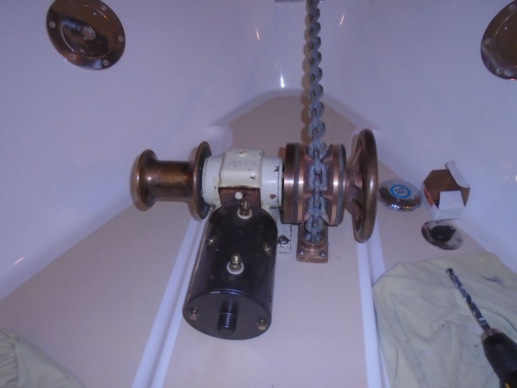
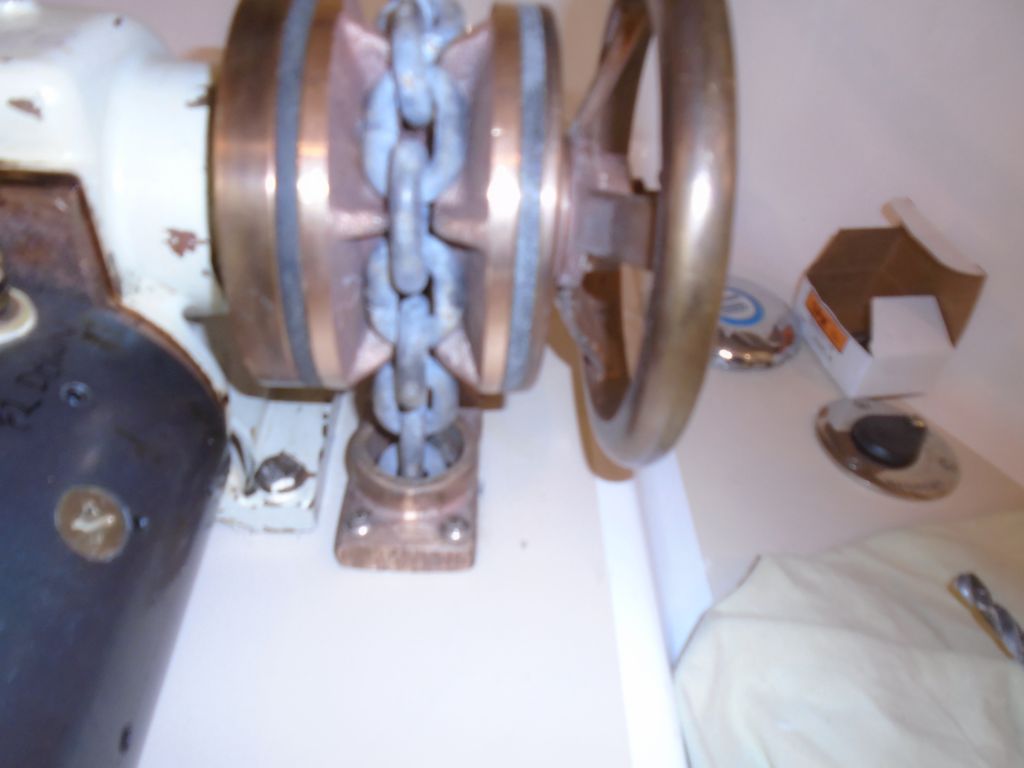
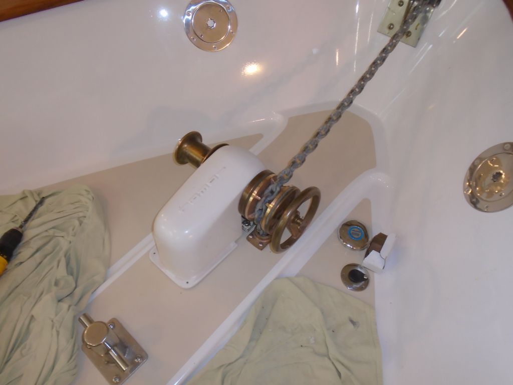
The relationship between the chain stripper and the
wildcat (and therefore the remainder of the windlass)
was a key one, and fairly precise. So although I'd
done all the layout already, now that it was time to
drill the actual bolt holes for both units I had to go
through the process again to ensure that the top of the
stripper fit properly in the wildcat's groove without
hitting anywhere, while maintaining the wildcat's
orientation to the chain coming over the bow. So I
played around and fudged things as needed to make this
just so before marking the bolt holes again (a task
easier said than done, since access to the holes was
tight in most areas--I used a 2" stub of pencil with a
very long tapered point to reach into the holes as
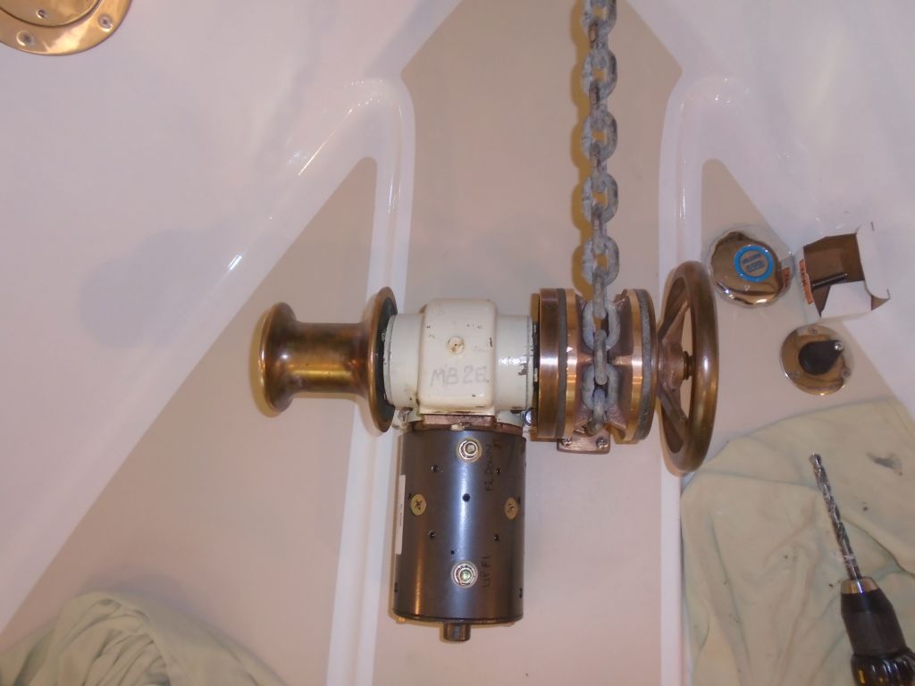
required). Afterwards, I temporarily pinned things
in place with some short bolts stuck in the holes (not
the final bolts) so I could check everything one more
time, run the chain actually through the stripper and
into the chainlocker, and contemplate the windlass cover
and wiring exits through the deck.
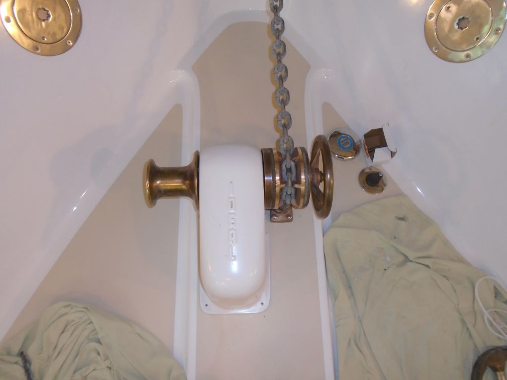
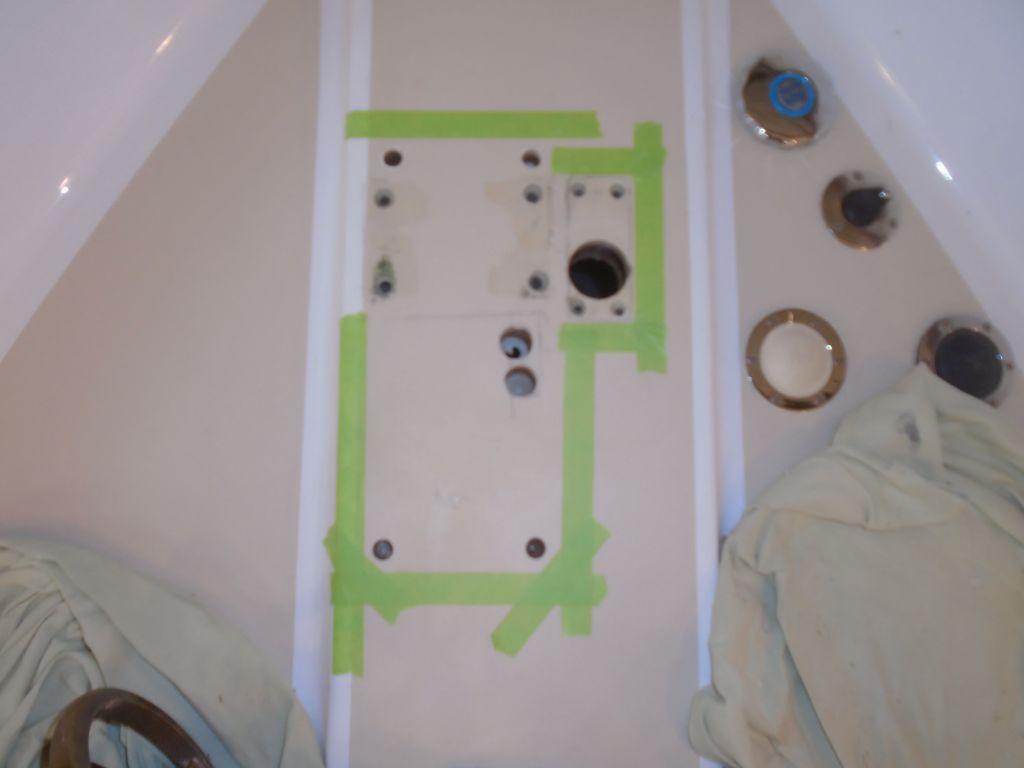
The windlass cover, a fiberglass molding, slipped over
the gear housing and motor, and I'd eventually secure it
to the deck with four machine screws to allow for ready
removal. For now, I needed to see what sort of
clearances within it required, as I had to figure out
where to bring two large cables through the deck to
attach to the windlass motor. I made some
reference marks in pencil and masking tape as needed to
show the outline of the cover, and marked the screw
holes as well for deck preparation.
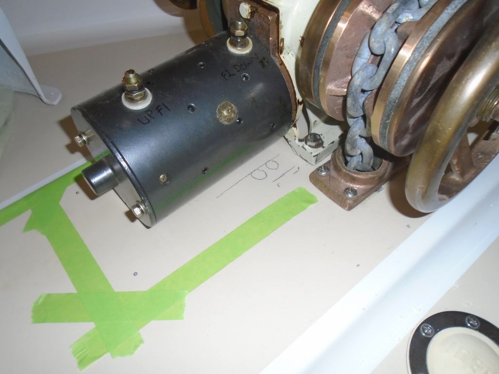
There was little room left for the cables' exit, between
how the motor and cover interacted with each other, and
the fact that the chain locker space ended before the
aft end of the motor (where there was the most room),
obviating that location as a possibility. Plus, of
course, the cables had to connect to the two studs on
the motor, so that further dictated possible exit
points. The aft end of the nearby foot switches
more or less demarked the chainlocker bulkhead for all
intents and purposes.
As it happened, the only practical place to bring
through the two wires was just aft of the windlass gear
housing, and sort of under the curve of the motor just
behind. I had hoped to use a cable through-deck
seal (i.e. cable clam) to run the wires and seal them
effectively, but there simply wasn't this kind of room
inside the fiberglass cover, so I'd rely on
epoxy-isolated through holes (which I'd planned
regardless) and plenty of sealant to do the job when the
time came. The area in question would be hidden
beneath the cover, so I could gob on the sealant with
impunity.
Removing the windlass parts once more, I drilled through
the deck (leaving the inside deck skin in place) in two
places with a 1" bit, which would give a large enough
void, once filled with epoxy, to allow me to run through
the cables with their 5/8" diameter, leaving plenty of
core-isolating epoxy around the edges. I also
drilled partway through the deck for the four windlass
cover mounting screws at the corners. Then, I
filled the resulting new voids with a thickened epoxy
mixture. Because I planned to tap the cover holes
for machine screws, I used a high-density filler for
this particular epoxy mixture; this material would
also help hold down the exothermic reaction of the epoxy
in the large holes for the cables. I left the
epoxy to cure overnight; this should be the final
pre-installation step, and with new bronze bolts on hand
for the job, I looked forward to wrapping this up next
time.
During my water system priming the other day, and in a
moment of abject brain-deadedness, I'd briefly tried
running the water system--including the galley sink's
foot pump--with all intake valves closed. This had
caused the pump to gasp and shudder and stick with the
pedal in the down position, inoperable. At the time, I'd left
it be pending more pressing needs, but now I
investigated the problem, as I'd not yet pulled water
through the system with this pump.
Fortunately, the only issue was a kinked output hose on
the back of the pump, which I quickly remedied and
returned the pump (or more accurately initiated the
pump) to full operation. This could be my most
awesome video presentation yet!