Project Log: Monday, February 20, 2012
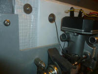
Now that my new fiberglass backing plate for the Webasto
fuel supply components was ready, I dry-fit the panel
and determined where the fuel pump should be located.
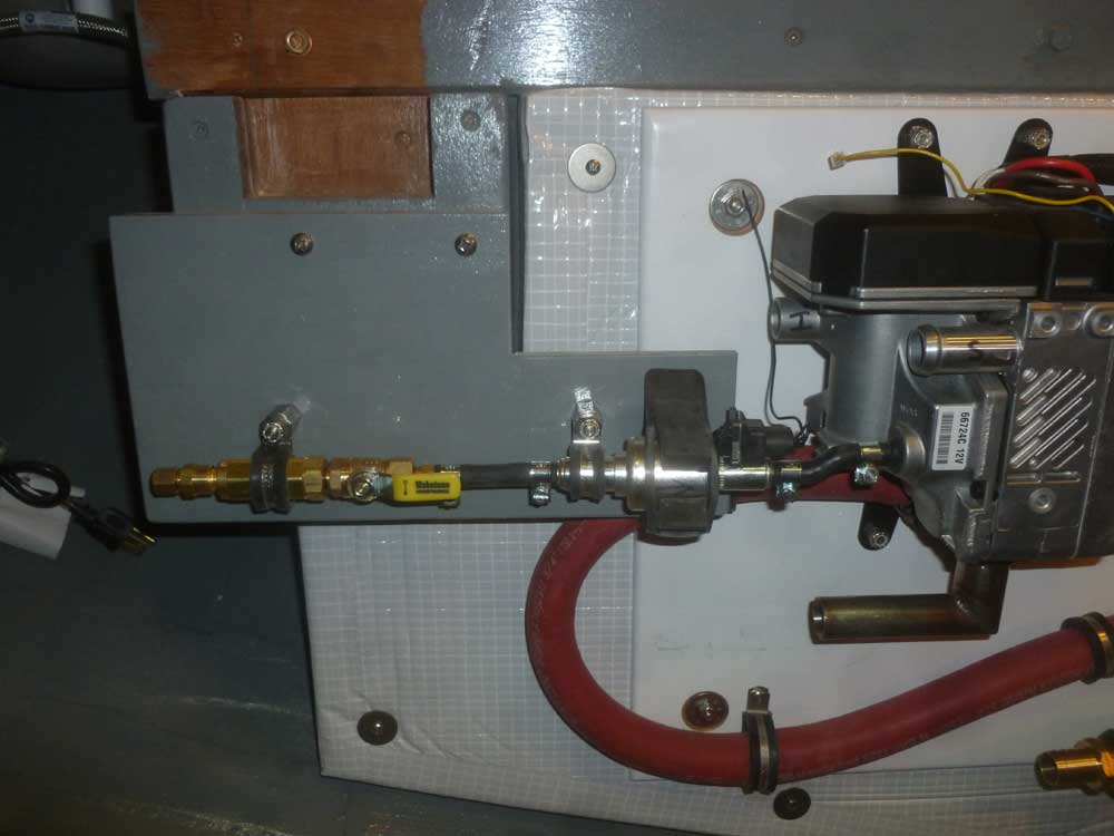
The instructions for the pump called for it to discharge
at an upward angle. The fuel line, as supplied,
was 3/16" copper, which I'd use between the tank and the
filter assembly, but the various components needed to be
interconnected with short bits of hose, also supplied.
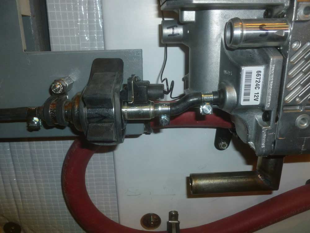
Because I could mount the fuel pump so close to the
boiler itself, I used a short piece of the hose to
connect it directly, and held the pump low enough so the
hose angled upwards.
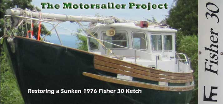
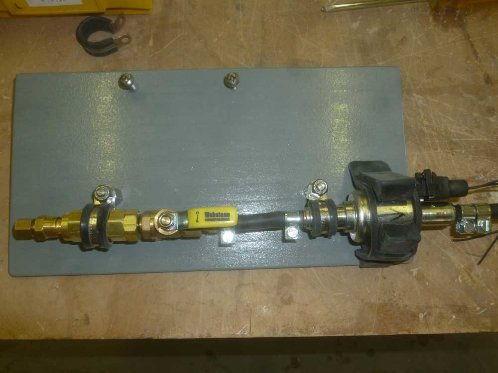
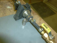
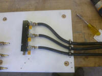
With the general placement on the backing panel
determined, I removed everything to the bench and
secured the pump in a supplied rubber mount in the
appropriate location. Because of the height of the
rubber mount, I secured the fuel filter to a stainless
steel standoff with a rubber-lined clamp, keeping the
remainder of the fuel system in line with the filter |


 |
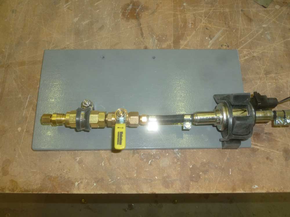
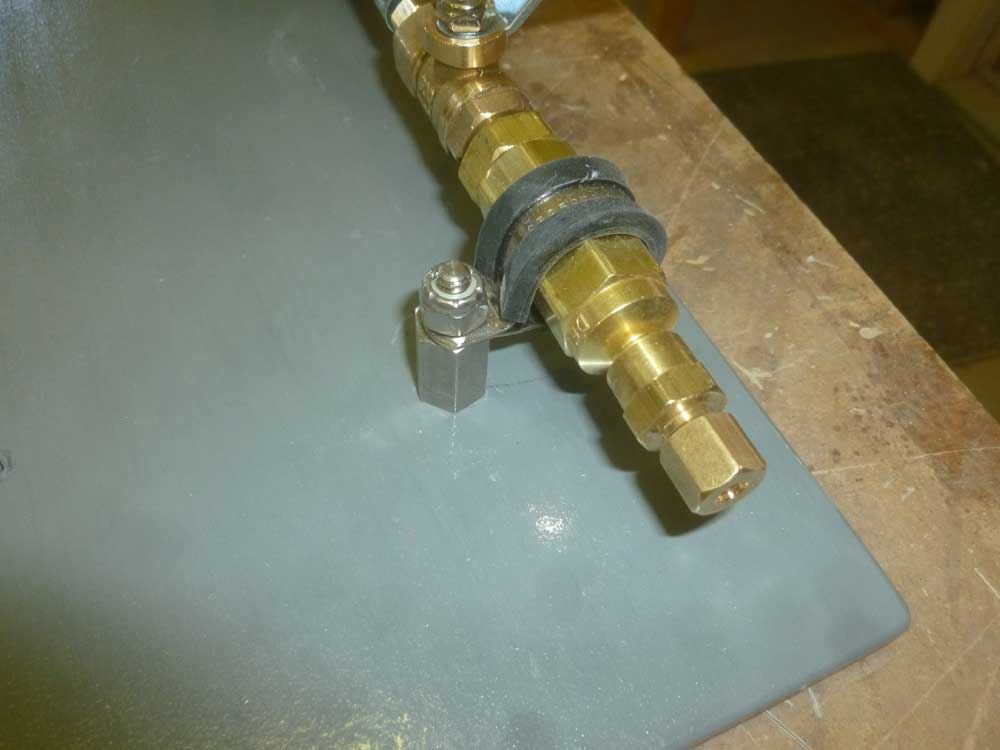
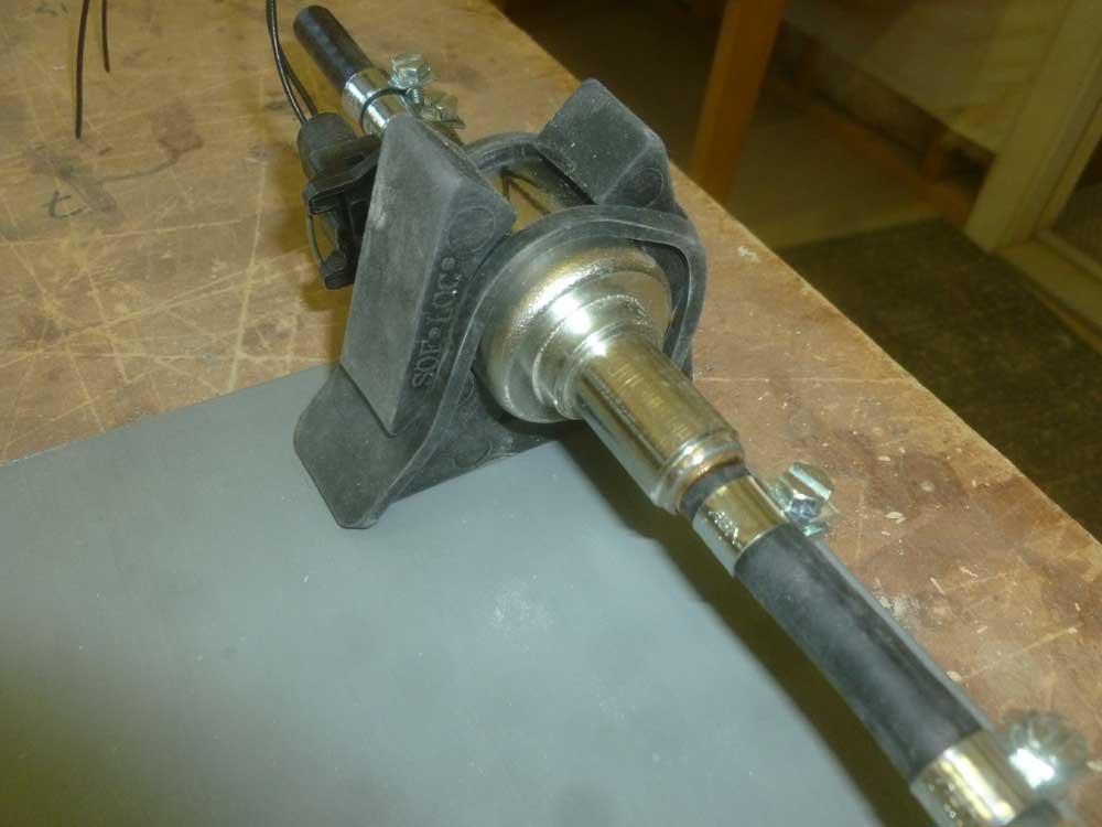
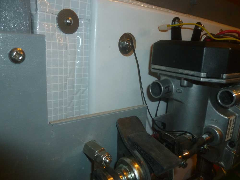
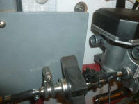
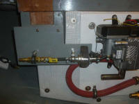
Temporarily installing the panel, I found that attaching
the fuel line to the boiler caused the fuel pump's
mounting ring--which was secured with only one screw by
design--to twist, affecting the alignment I'd planned.
I also noticed that the forward end of the panel above
the fuel pump would affect the installation of the
boiler's air intake line, so I took everything apart,
cut off the offending corner of the panel (which served
no purpose anyway), and added another clamp to the fuel
pump, also secured to a standoff. |

 |
I'd wait to install the fuel line between the tank and
the filter till later in the project. |
 |
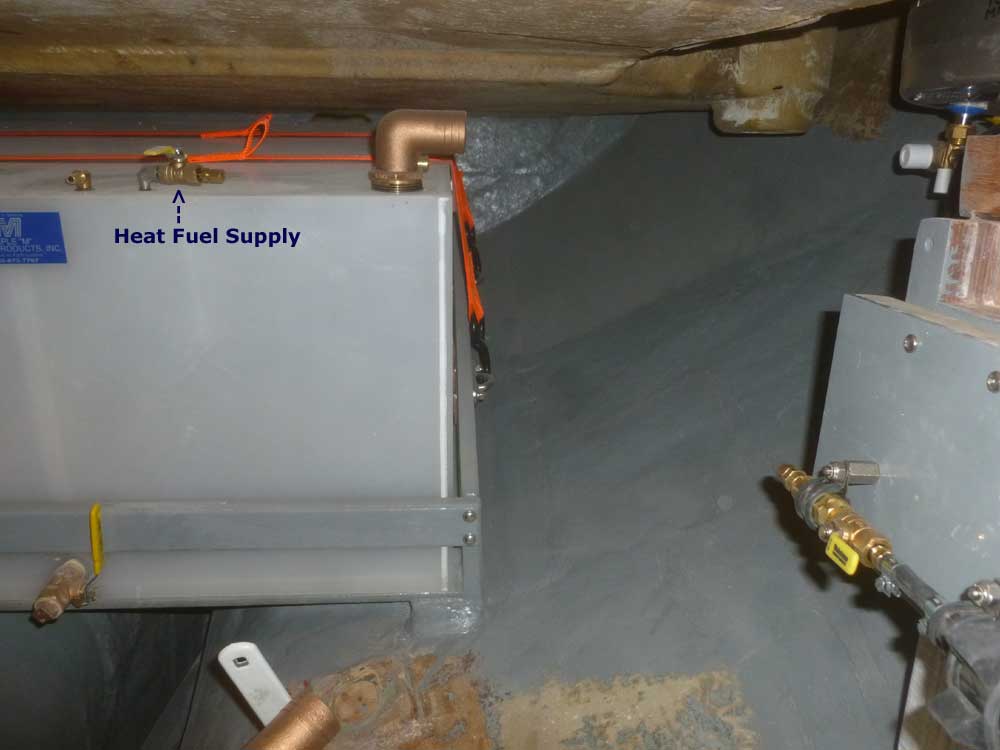
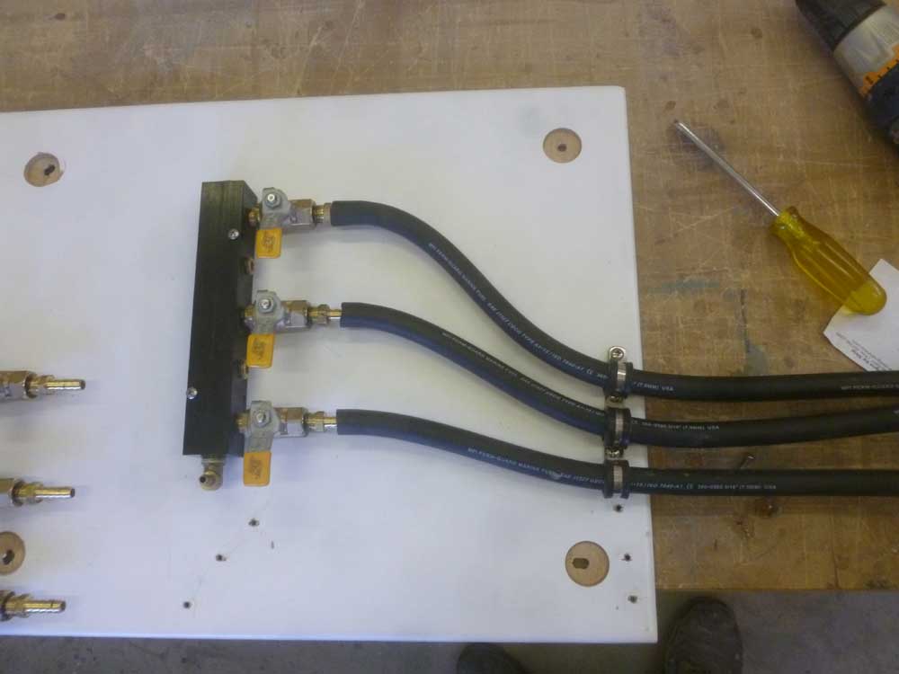
Next, I turned to the main fuel system manifolds.
Despite what seemed an abundant space on the starboard
engine room panel, it was still a bit of a trick to
figure out the best way to handle the fuel distribution.
With three tanks, and both supply and return manifolds,
there'd end up being many hoses running around, and I
wanted the layout to be logical and attractive.
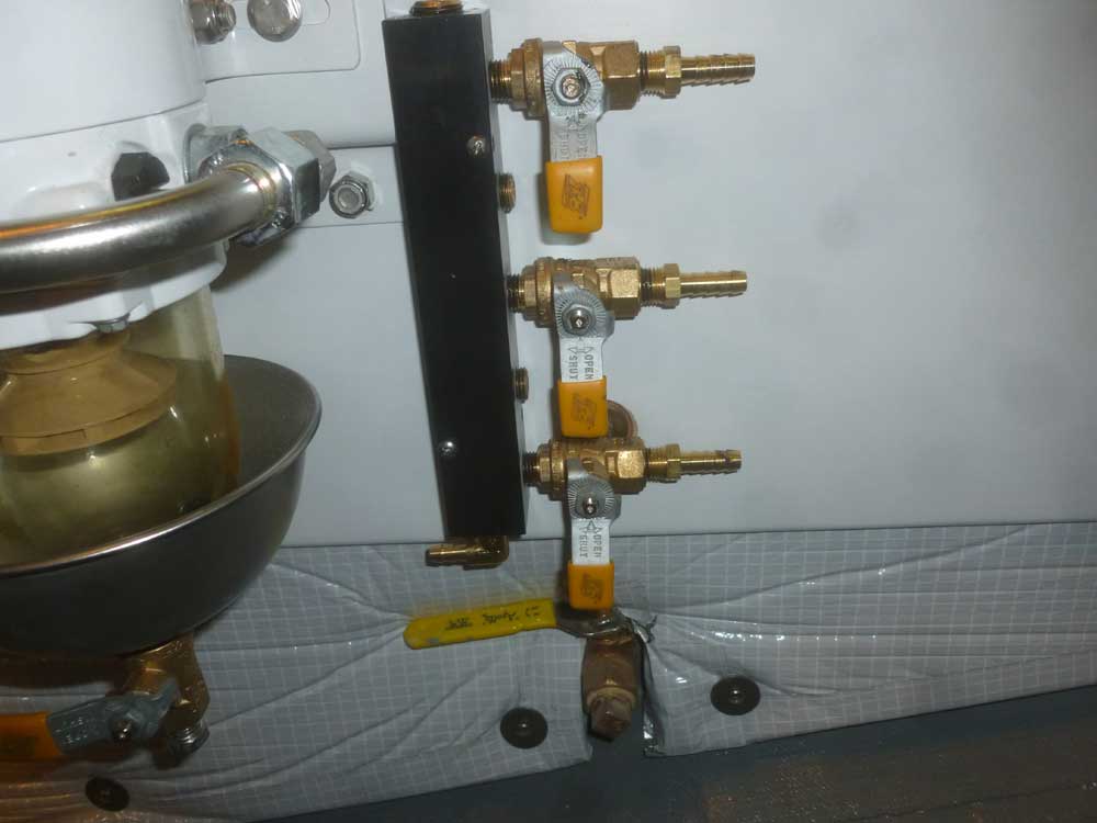
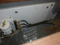
I'd assembled the manifolds some time ago, but had left
certain components off pending the final layout of the
system. After considering various options, I ended
up installing the supply manifold just aft of the
filters, with the outlet facing down and three inlets
facing aft to accept the fuel hoses from the tanks.
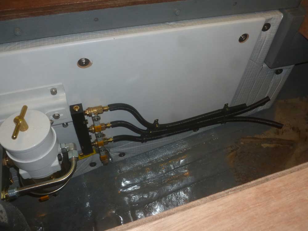
With some short pieces of fuel hose for layout purposes
only, as I wasn't yet ready to run the actual fuel
lines, I determined the hose runs from the
manifold, running all three hoses down towards the
bottom to maintain as much panel space as possible.
|

 |
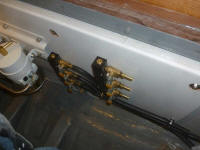
At the manifold outlet, I installed a 90° fitting to run
the fuel line to the nearby filters. However, I
wanted to install a manual priming bulb to help fill the
filters after maintenance, and wanted the bulb to be
isolated from the regular fuel run by shutoff valves, so
eventually I figured out what plumbing parts I needed to
effect this and ordered them to later use. I'd
complete that part of the installation once the parts
arrived.
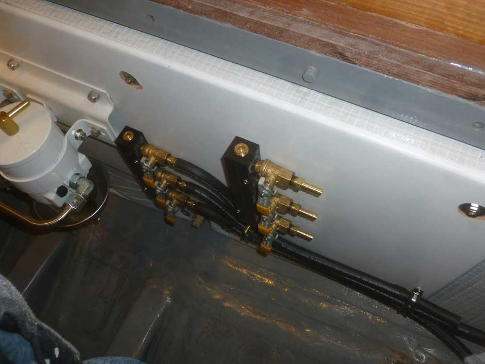
While I still had the temporary hoses in place for the
supply, I determined a location for the return manifold,
just aft and slightly above. This location would
allow fairly direct connection to the return port on the
engine, and also provide an advantageous hose run away
from the manifold. Having determined what I needed
to with the panel in place, I removed the whole fuel
panel so I could more easily install the final
components on the bench in the shop. |
 |
Planning ahead for the raw water strainer installation,
I tried to keep as much of the aft end of the panel
clear as possible, but even so there wasn't sufficient
room. But it'd be easy to install the strainer on
some 1" standoffs, which would mean the filter could
hang over the fuel lines as needed, so ordered what I'd
need for this task.
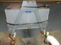
To support the mizzen mast step, there was a simple
wooden A-frame, which I'd removed from the boat during
the initial stages of the project. Now seemed like
a good time to reinstall it. I could re-use it as
is; to install it, I applied epoxy adhesive to the top
of the fiberglass flange that fit beneath the deck, and
held it temporarily with bolts through the mizzen step
holes. At the bottoms of the legs, I installed
additional adhesive to secure them to the pads that were
still in place from the original installation, and left
this to cure overnight, secured with some tape to hold
things in position. No, it's not straight, but
blame the original builder for that: it's in the
same location as per original. I'll just have to
live with it.
Later, I'd install new tabbing to complete the
installation. |
 |
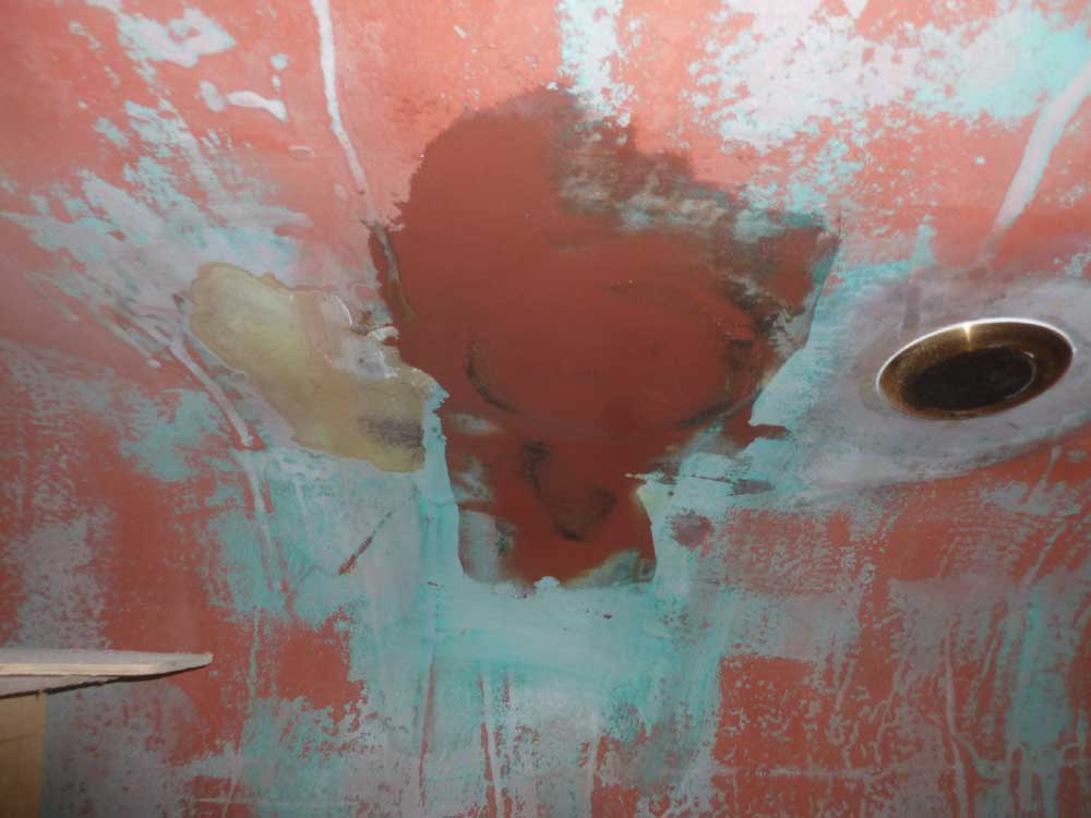
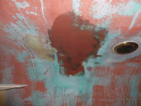
This whole process took far longer than I'd expected,
but I had enough time to sand the new hull patch over
the old depth sounder location, and apply a first coat
of fairing filler. |
|
Total Time Today: 5.25 hours
|
<
Previous | Next > |
|
|