Project Log: Saturday, January 26, 2013
I continued work with the wiring, this time focusing on
the fan heaters and their required wiring. During
an earlier wiring stage, I'd completed some of this
wiring in advance, specifically related to the
pilothouse fan heater control, for which I ran a pair of
wires down to a nearby terminal block.
To complete the pilothouse fan heater wiring, as well as
wire in the main cabin fan heater and its control, there
were additional wires to run. Each fan heater
required a pair of wires, plus a 2 amp fuse for device
protection.
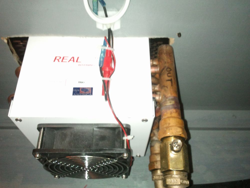
Completing the pilothouse heater wiring was simple
enough, given its proximity to the console and the fact
that the two wires to the control had already been run.
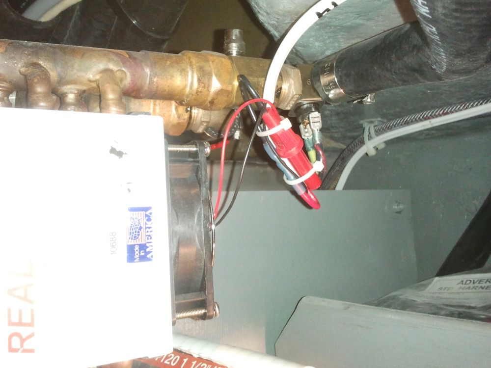
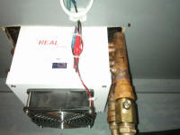
I installed a fuse holder near the fan itself, and in
this case, since this was the first fan heater in the
heat zone, I ran the wires through an aquastat control
clamped to the pipe above; this would prevent the fan
from operating till the water temperature within reached
a certain threshold, so the fan wouldn't blow cold air.
I connected the positive wire to the appropriate
terminal in the console, and the ground to a negative
distribution buss. |
 |
For the main cabin, I ran a sheathed wire pair into the
cabinet, following a path partly determined by the
depthsounder transducer cable that I'd run earlier.
This fan heater didn't require an aquastat, since it was
on the same zone as and downstream from the pilothouse
heater. (Though during the planning stage I'd
considered two separate heating zones, I deemed this
frivolous and went with a single zone in the interest of
relative simplicity.) As before, I connected these
with a 2 amp fuse. |
 |
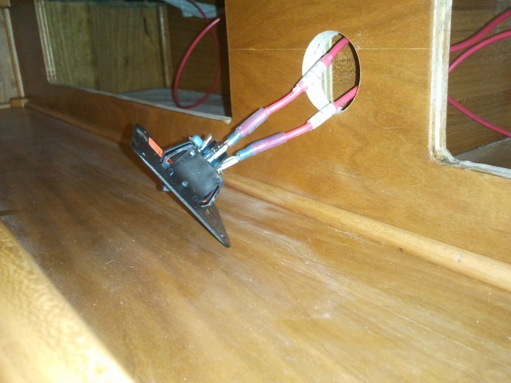
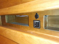
I had another fan control (low/high) for this heater,
and decided to place it above the dinette, near a USB
charging port I'd previously installed, and creating a
mini "control center" of sorts. This meant that I
had to run two red wires out to the new control from a
terminal strip in the console: one wire for 12V
power (eventually connected to the main distribution
panel and a dedicated circuit breaker for the two fan
heaters); the other wire for the heater control itself,
i.e. the other end of the red wire I'd just connected to
the heater. As in all cases, I determined these
wire runs and their destinations based on various wiring
diagrams supplied along with the diesel boiler and fan
heaters; as needed, I extrapolated and massaged the
information to fit my own installation specifics versus
the generic wiring diagrams. |

 |
To round out the fan heater wiring, I ran wires from the
appropriate terminal blocks to the main distribution
panel--two power supply wires, one for each fan
heater--and connected them to the proper circuit
breaker.
Still remaining to complete the heating system wiring
was the thermostat installation and related wiring,
which would be the final stage of this process.
|
| |
Total Time Today: 4.5 hours
|
<
Previous |
Next > |
|
|