Project Log: Sunday, April 19, 2015
In April 2014, I'd wired up the new automatic bilge
pump. I'd pre-wired the Cole Hersee bilge switch I
installed earlier, since it had to be wired from the
back side only because of its design, and I'd run its
wires to a terminal block in the console without any
particular regard to which wire was which, though I'd
noted the wire colors at the switch and terminal for
future reference.
The pump itself had three wires, and I used a
three-conductor cable to extend these wires forward and
into the console where, back then, I'd wired them to the
terminal block to conjoin them with their appropriate
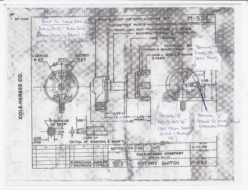
terminals on the switch itself. For this, I relied
on the crude wiring diagram supplied with the Whale
pump, plus a schematic of the bilge pump switch from
Cole Hersee.
Later, once I'd energized the electrical system, I found
that the pump didn't switch on as it should have.
But before long I'd moved on to other things, and
troubleshooting the issue languished for some time--for
just over a year, as it happened.
Now, with the boat sold to a new owner and charged with
completing various tasks on board, I turned to the pump
wiring once more, with a fresh outlook. Obviously
I had something mixed up, whether it was the wires from
the pump or those from the switch. Studying the
diagrams from Whale and the switch itself, I eventually
determined that I had the hot wire--the lead directly
from the battery switch--led to the wrong terminal on
the pump switch. Previous information I had noted
on the switch's diagram had led me to connect the "1"
terminal on the switch to the hot wire from the battery
(#62). This was incorrect: the hot wire
actually needed to go to terminal "B". I made the
switch, and tried the pump again.
This time, the pump operated, but it was clear that I
had the other two terminals reversed: switching to
"auto" caused the pump to come on, while switching to
"manual" did not. So now, I reversed the other two
wires from the pump (those entering the bottom of the
terminal block in the photo). Red now led to the
black wire from the switch (terminal "1", auto), and
brown now led to the brown wire from the switch
(terminal "2", manual). Finally, it worked the way
it should.
I'd only installed one of this type of switch in the
past, and for some reason I'd mis-labeled the diagram
that I'd kept for future reference. This caused me
to wire the pump originally according tot he diagram,
but since that was labeled incorrectly it led to this
issue. I created a new diagram now more clearly
marked for this boat (specifically), and for any future
installations I might do using this switch.
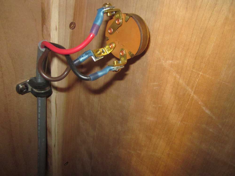
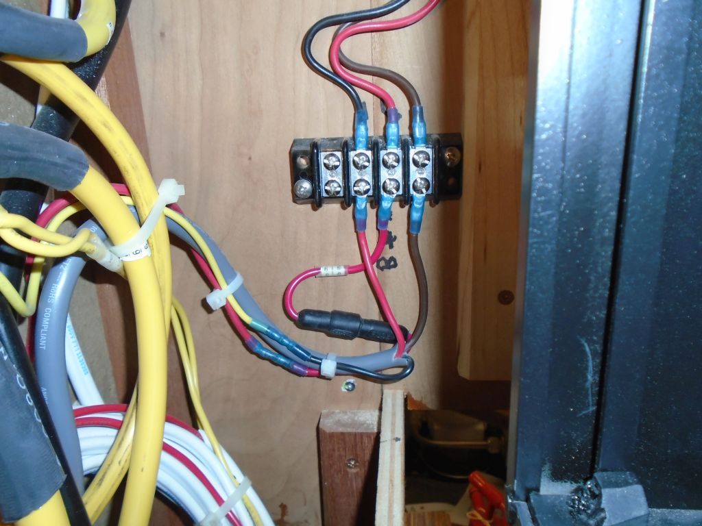
In the event, the three images below represent the
correct way to wire this particular switch and automatic
pump on this specific boat.
|


 |
Meanwhile, I prepared for some of the additional work on
board by specifying and ordering various materials that
I'd require in the near future. |
| |
Total Time Today: 1.5 Hours |
<
Previous | Next > |
|
|