Project Log: Saturday, June 2, 2012
With some momentum on the steering system from recent
efforts, it seemed like this was the time to continue
work and wrap up the main portions of the installation.
Specifically, I needed to mount the steering
cylinder--or, more accurately, determine what I needed
to do to mount it and compete the basic structural steps
required.
The after steering room was tight, thanks to the canoe
stern, and long ago I'd determined that the required
steering cylinder was too long to mount in a purely
athwartships or longitudinal manner. To get around this,
at an earlier stage of the project I determined I could
mount the cylinder at 45°to the boat's centerline, and
located a
new
bronze rudder arm that, with its diamond-shaped
shaft hole, fit this need perfectly. I covered
these steps, along with basic steering geometry layout,
in
earlier progress reports.
Even so, the travel required for the steering piston was
longer than any available dimension within the steering
room and within the limitations imposed by the angle of
the rudder arm. So I knew from early on that I'd
have to cut an opening in the after cockpit bulkhead to
allow appropriate passage of the steering cylinder and
piston. This posed no particular concern, since I
intended to build new, closed-in cockpit lockers to fill
in the spaces left behind by my earlier removal of the
original teak-slatted seating surfaces. Whatever
opening was required for the steering cylinder would be
hidden within the new locker.
Basic measurements and fittings during earlier sessions
had given me the idea that I could get away with a
simple round hole through the bulkhead, through which
the piston end could pass as the rudder turned, so that
formed my starting point for the installation.
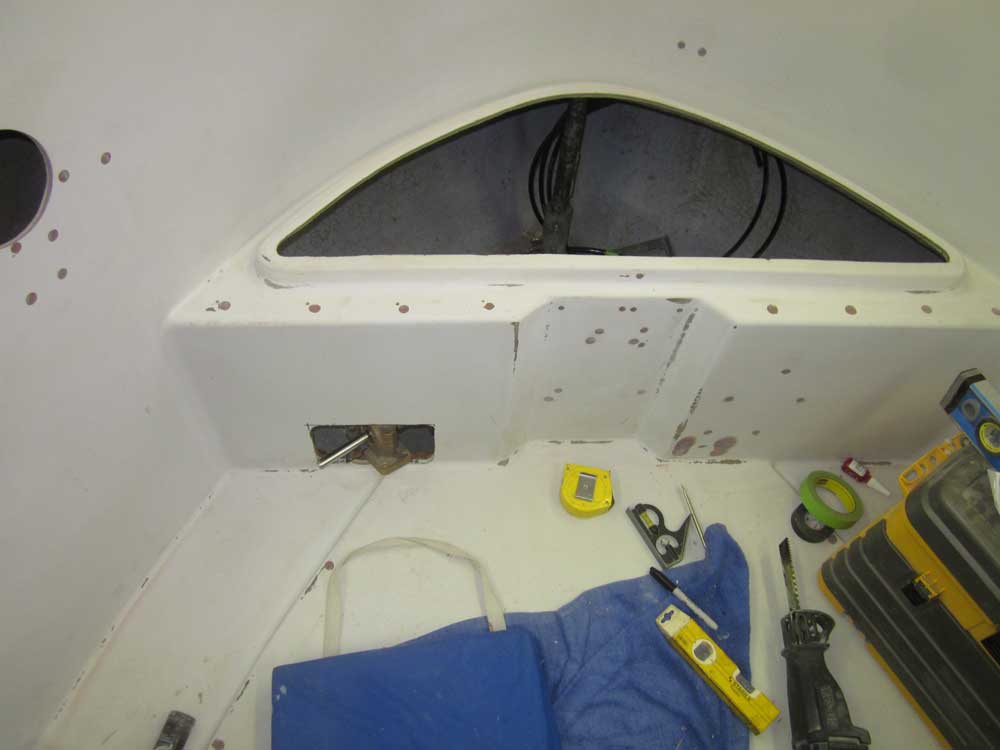
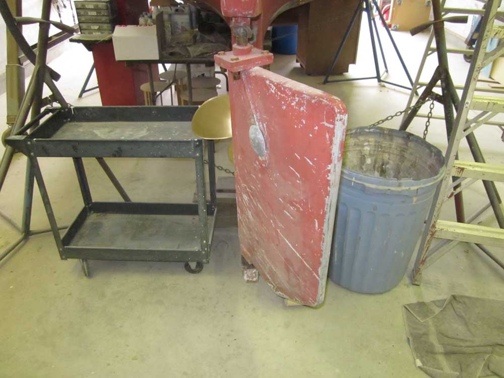
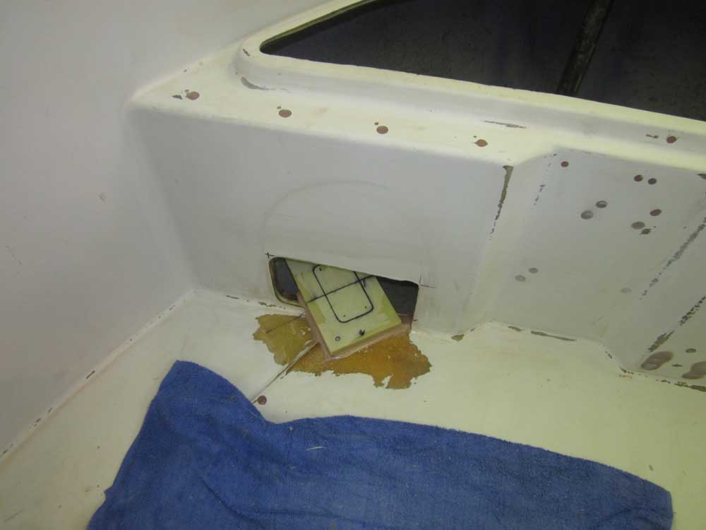
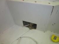
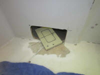
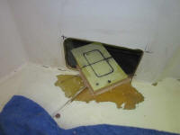
Working off existing layout lines I'd created during the
preliminary pre-specification stages of the steering
project (more on this presently), I extended some marks
to the after bulkhead that represented the general area
where I'd need the cut. |
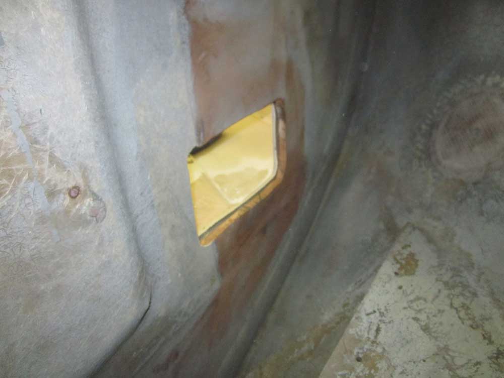
The orientation of this photo is
forward
and to starboard
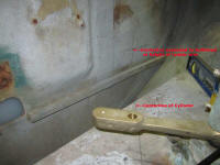 |
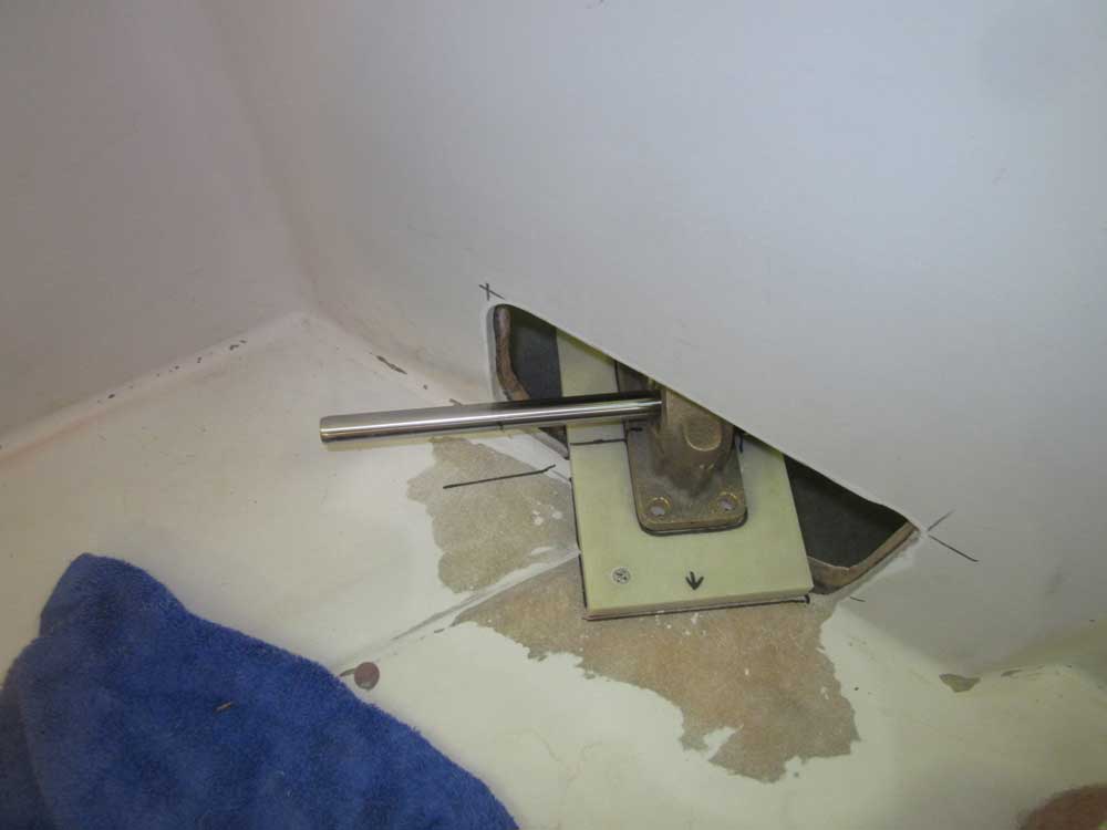
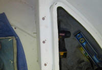
Using just the arbor for my hole saw, I drilled through
the bulkhead from the aft side to make sure the hole
landed in a usable spot on the other side. Then, I
drilled a 2" hole through the bulkhead and prepared to
do the initial layout of the cylinder. The main
goal of all this, eventually, was to determine the
requirements, location, and construction of any supports
required for the cylinder bracket. |
 |
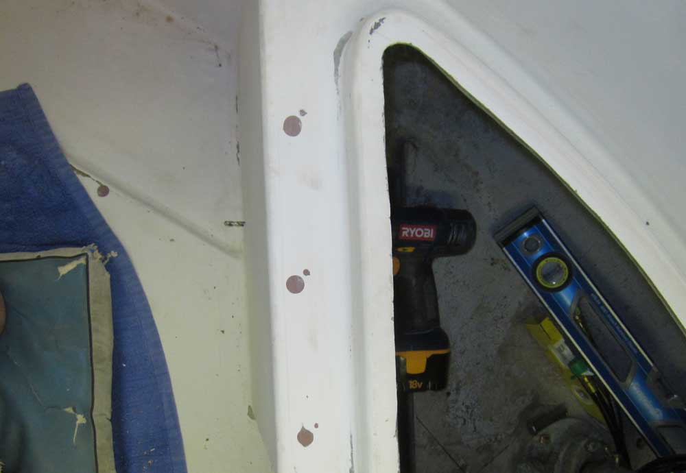
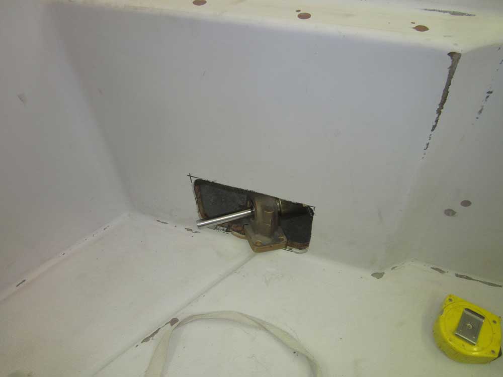
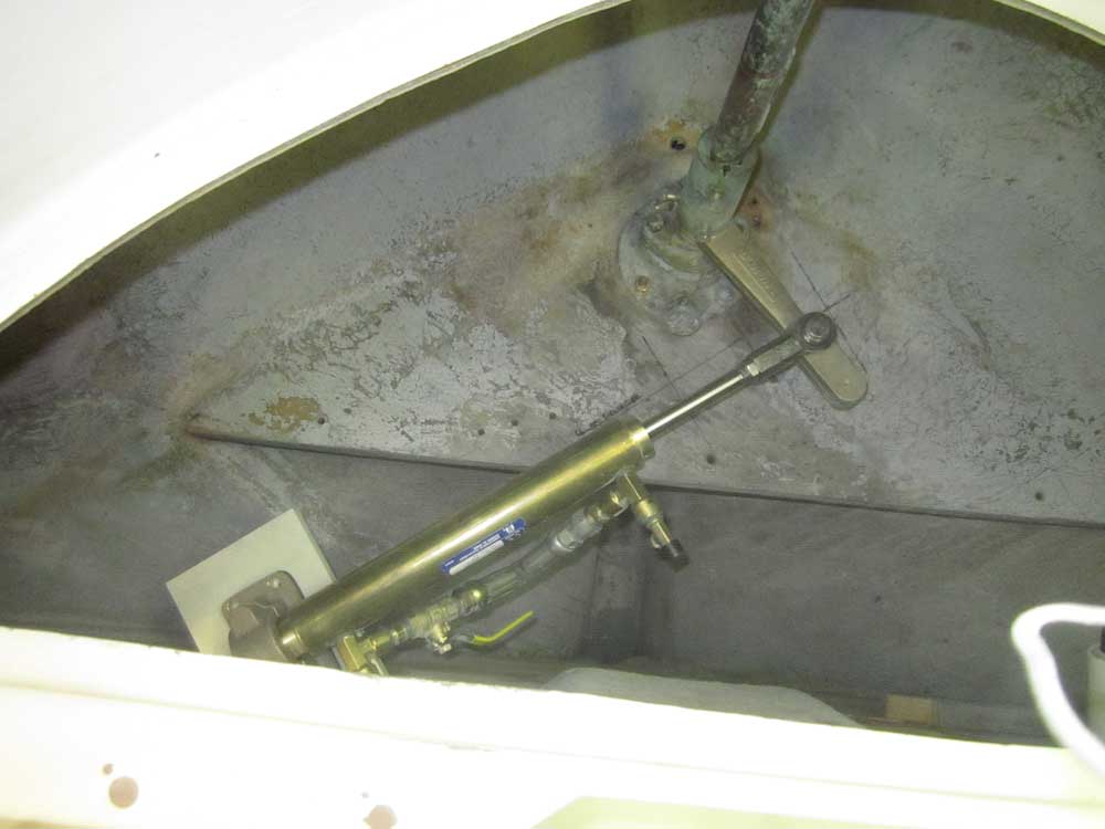
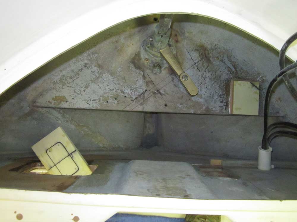
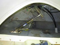
Basic cylinder layout required that the cylinder/piston
assembly be mounted so that the cylinder would be
aligned through the center points of the steering arm
connection pin at the rudder's hard over position in
both directions. This was the dark line I'd used
to do my initial layout, and earlier I'd created this
mark by using measurements provided by the steering
manufacturer. To provide full travel of the
piston, the instructions called for me to extend the
steering piston from the cylinder to a 21" measurement
from the center of the bearing support, with the rudder
(and rudder arm) centered. Remember throughout the
following photos and description that the rudder arm is
offset 45° to port when the rudder is centered. |
 |
With the cylinder extended as required, I attempted to
fit it into position. Immediately there was a
problem: with the extended piston, the mounting
bracket essentially ended up in the middle of the
bulkhead, crushing my dream of a small hole for the
passage of the piston. As I struggled with
visualizing how this would work, I worried for a time
that the required height of the bracket might also mean
that I'd have to cut through some of the cockpit sole,
which led to further worries of interference with the
fuel tank below. After some additional
measurements and a few desperate moments, I determined
that neither of these issues would come into play,
fortunately.
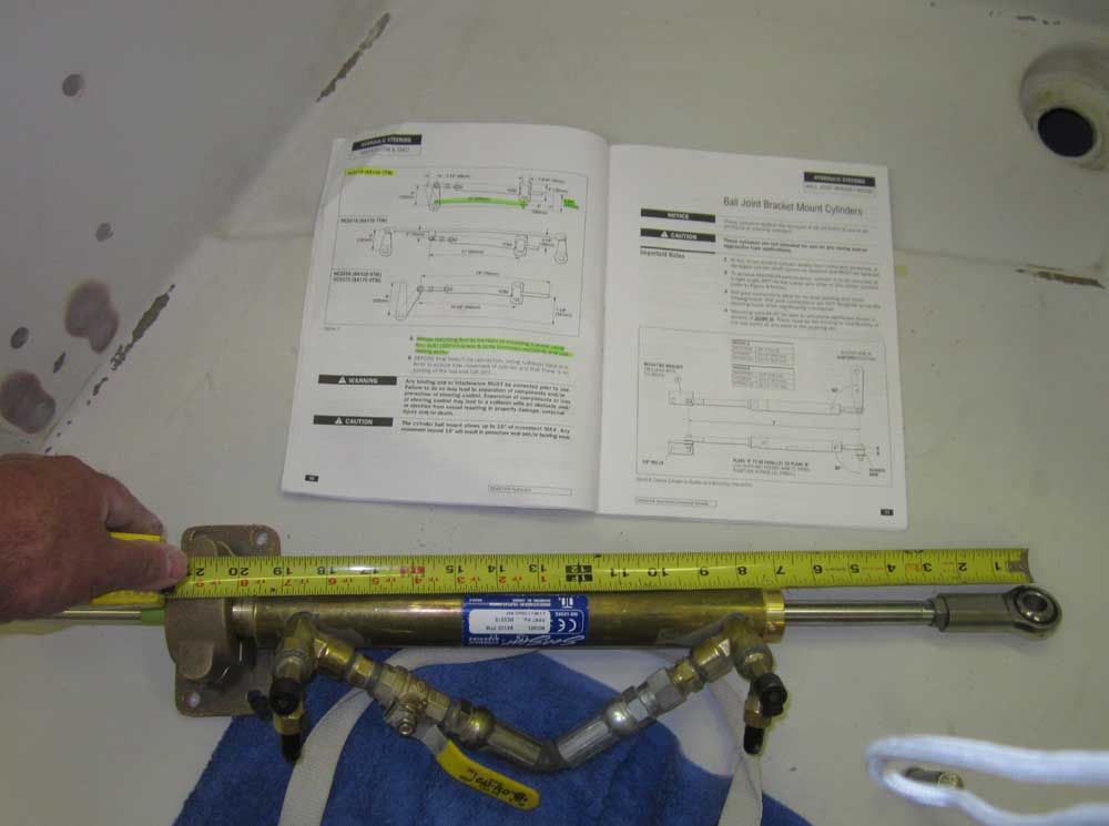
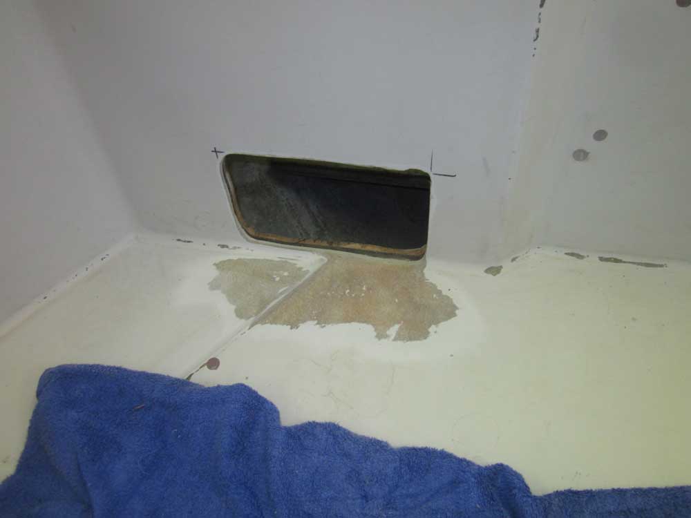
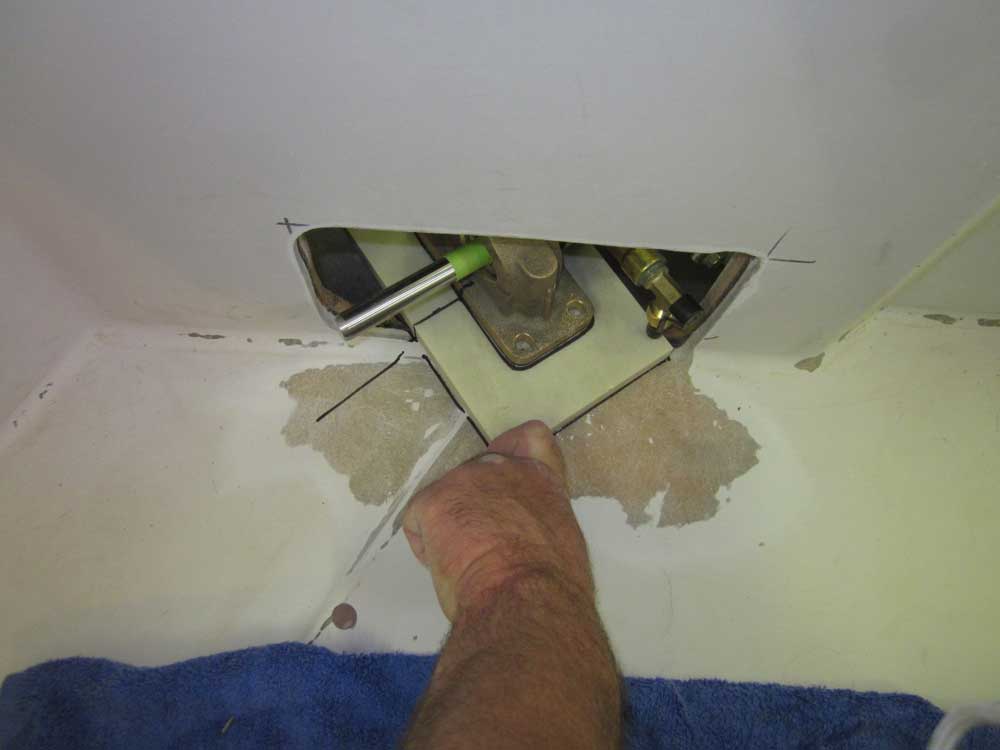
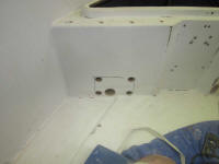
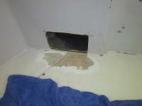
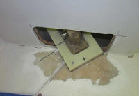
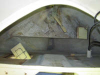
The long and the short of all this was that I had to
greatly enlarge my opening through the bulkhead to
accommodate the mounting bracket/bearing. So after
additional measurements and layout, I marked the four
corners of the new opening with 1" holes, and cut the
balance with a saw. Later, I even extended the
inboard side of the opening by about an inch to better
accommodate a large base plate. |
 |
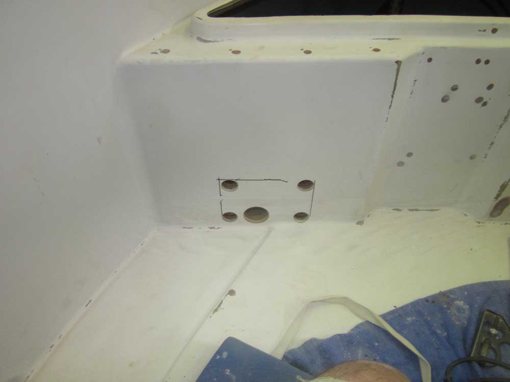
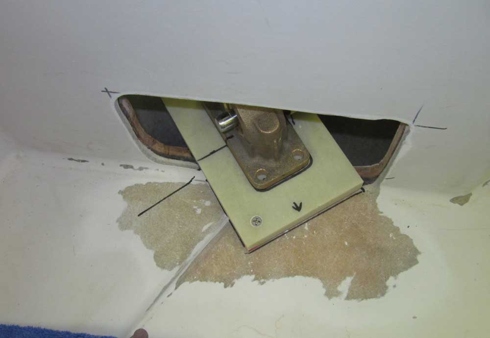
With the opening cut, I could finally fit the cylinder
in its proposed location. Fortunately, the height
of the bottom of the opening, even accounting for a 3/4"
base plate, would be appropriate for the cylinder in
relation to the height of the steering arm.
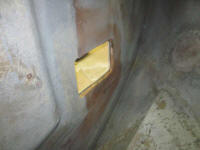
The initial layout pointed to the need to extend the
opening to port (towards centerline), which I did; then,
to prepare ahead for a fiberglass base plate, I ground
away the gelcoat from outside the opening, and the paint
from inside, and also smoothed the cut edges.
Pay no attention to the orientation of the fittings on
the cylinder in these photos, as this does not represent
the final orientation of the hose connections and bypass
valve; the cylinder rotated freely on the piston, so
there was nothing to hold it in one position or another,
but I'd orient the fittings in an appropriate way during
final installation.
Another note: it's my own doing that the bypass
valve/hose kit is installed in the direction it is.
Dedicated readers may recall some time ago the issues I
had with my own attempt at installing this kit, and
Teleflex was nice enough not only to provide me with a
replacement cylinder at no cost, but also to
pre-install the bypass kit for me. At that time,
they had asked me which direction I wished it to face,
and I chose the forward direction as it'd seemed the
best option based on what I knew. I'd not
necessarily anticipated that the cylinder would be so
close to the bulkhead, and depending on how I had to
align the cylinder fittings the valve itself actually
could run into the bulkhead (normal operating position
is with the valve closed, or with the handle turned 90°
from where its shown in these photos). This would
work itself out without major issue, but I was basically
stuck with the position it was in.
|

 |
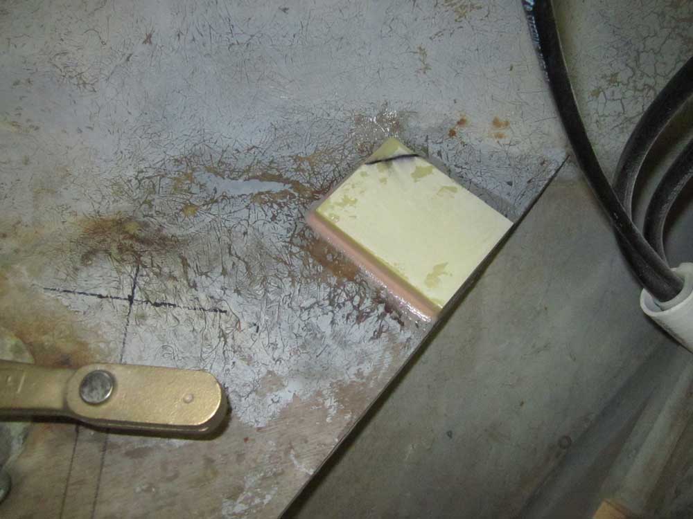
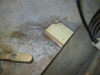
From a piece of 3/4" G10 epoxy laminate, I prepared a
base plate for the steering cylinder's mounting bracket.
I chose this material for its excellent strength, since
it would form the basis for the entire steering system.
Cutting the 8" x 5" piece required for the cylinder
mounting left me with an offcut that seemed perfect for
the autopilot pump mounting, so I reserved it for that
purpose.
After making some layout lines, I test-fit the base
plate in the opening and with the cylinder in place.
Again, ignore the position of the cylinder hose fittings
in most of these photos. |

 |
Happy with the basic positioning, I drilled for a single
screw to hold the base plate in position for my
convenience, and eventually to secure it while I epoxied
it in place, since the cantilever of the base plate into
the steering room made it unstable. |
 |
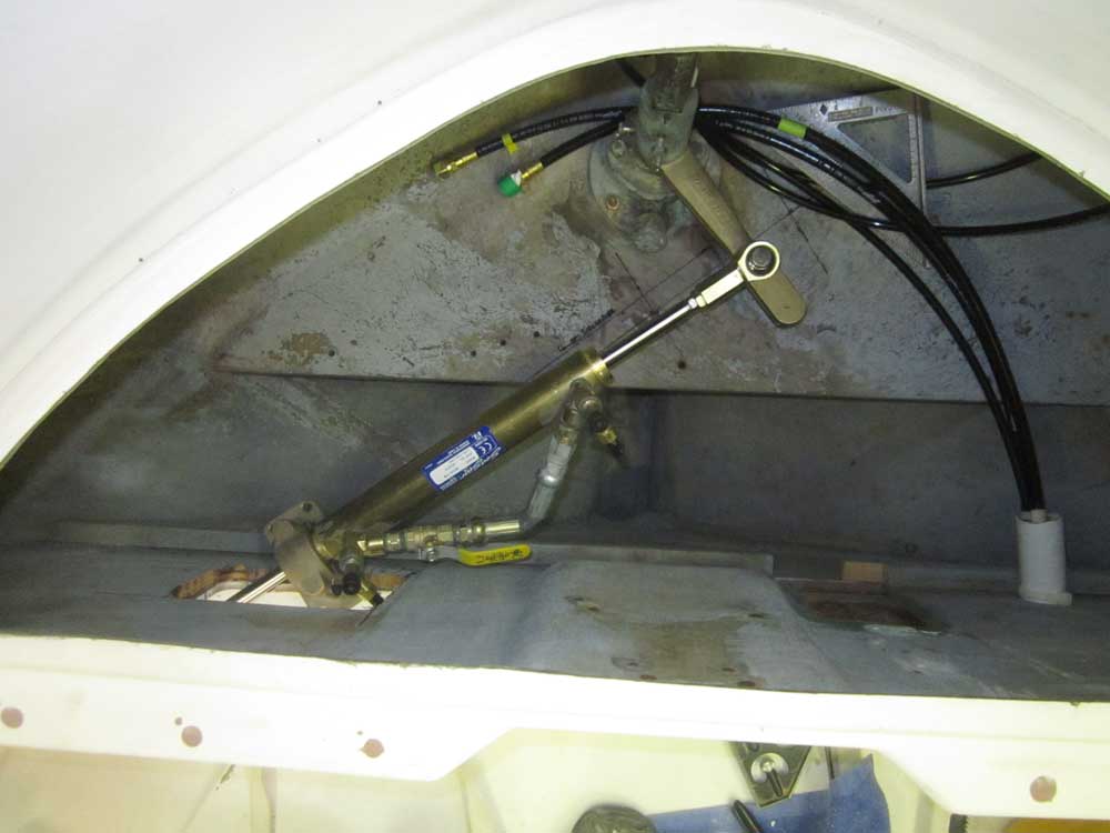
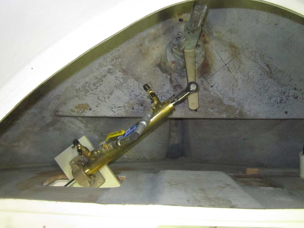
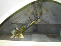
Relieved of the need to hold the plate constantly, I put
the cylinder back in place and, holding the bracket in
its appropriate position, moved the rudder (and
therefore the cylinder piston) through its full range of
motion to check for any issues and, most importantly, to
determine that the bracket was in the correct location
to allow full travel. Note the changing position
of the piston between the photo sets, and how the
cylinder and piston are in line with the layout line on
the rudder platform when fully extended to each side
(which was the desired result). |
Hard to Starboard
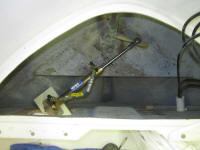
 |
Hard to Port

 |
That all seemed to work out well, with no binding or
interference, and the travel was full and appropriate.
Sometime later, I'd add a permanent rudder stop to
eliminate the possibility of overtravel when turned hard
to starboard.
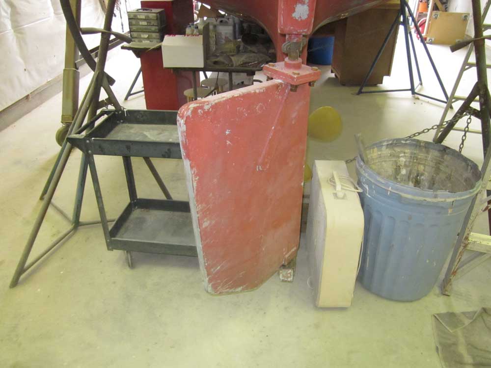
After cleaning up and solvent-washing, I secured the
bracket baseplate with epoxy adhesive and left it for
the time being; later I'd add fiberglass tabbing to
secure the whole thing. Off to the port side, in a
location I'd determined would be convenient, I epoxied
in the base plate for the hydraulic autopilot pump after
preparing the surface beneath. This base plate was
probably not necessary, but with the perfect size offcut
on hand, it made sense to install it for additional
strength, as well as to raise the pump off the platform
a bit. |

 |
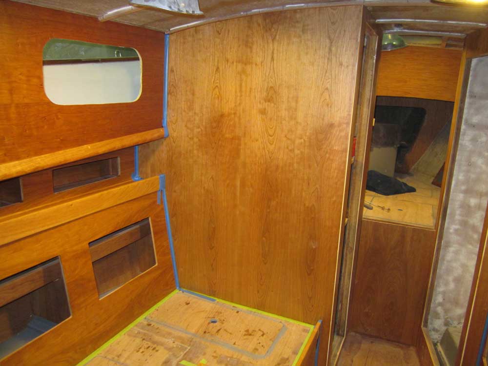
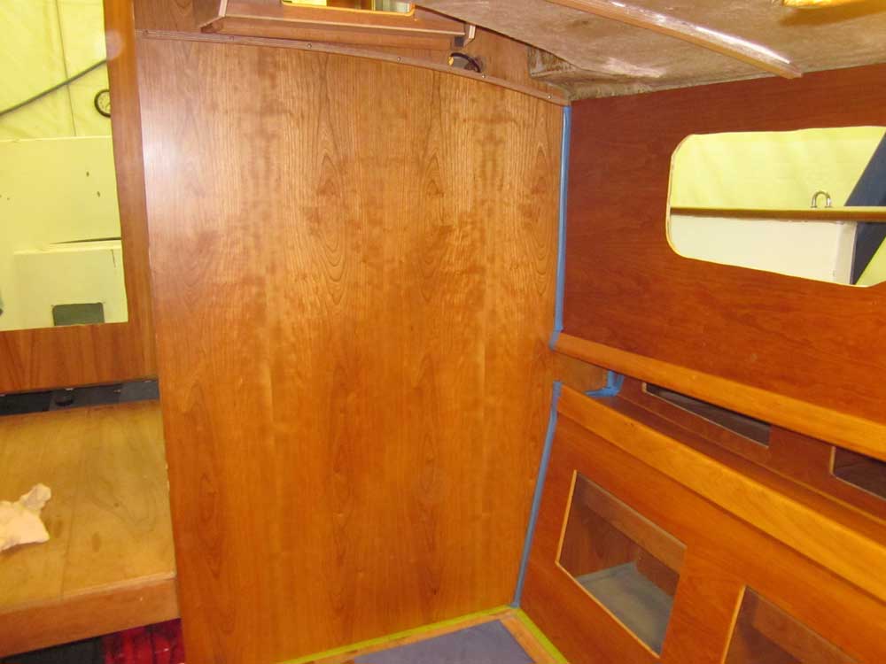
To wrap up the day's work, I sanded and revarnished the
two large bulkheads in the main cabin, as I'd not been
happy with the finish of the first coat of satin in
these areas. |


|
Total Time Today: 6 hours
|
<
Previous | Next > |
|
|