Project Log: Friday, December 30, 2011
I'd be getting back to work on some of the final details
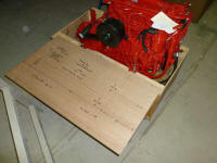
of the "pre" engine installation soon, so to prepare I
double-checked my engine template against the engine
itself--a worthy step to ensure that my measurements and
layout were accurate, and that no changes were
necessary. This is why I waited till the engine
was on hand before beginning engine foundation
modifications and construction.
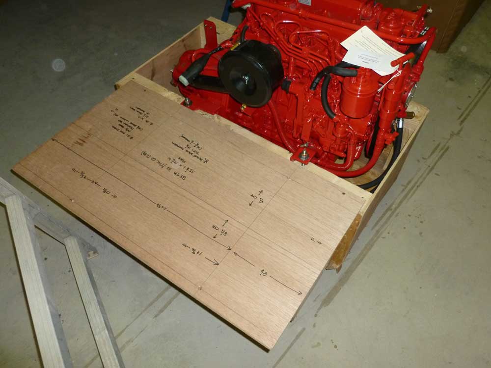
Securing the template temporarily against the engine in
its crate, I determined that my mounting locations were
correctly laid out, and that the overall dimensions of
the template matched the engine accordingly. |
 |
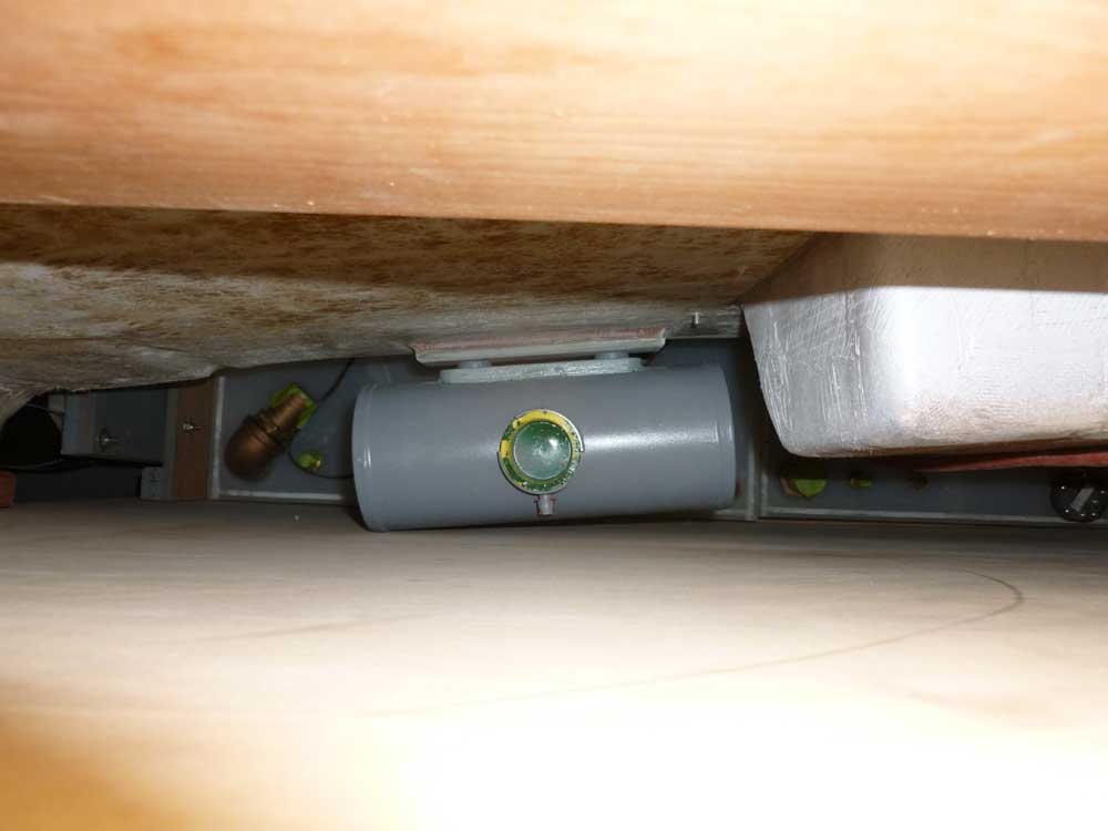
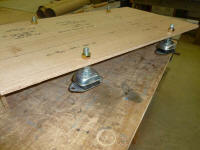
Next, I removed the temporary engine mounts I'd built
from scrap lumber and installed the actual flexible
mounts directly on the template. For initial
layout purposes, I liked to have the mounts adjusted to
some middle range, allowing for adjustment up or down as
needed when the engine was installed, so to achieve this
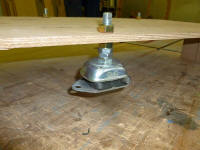
and keep all four mounts at the same level, I installed
a pair of slim nuts on the studs beneath the main nuts
that would support the engine. These nuts were
just spacers for now; later I'd remove them, which would
leave a corresponding amount of thread exposed for
adjustment.
Upon reflection, I wondered if the pair of nuts brought
things a little too high; it's ideal to have the engine
adjusted as low as possible on the mounting studs, but I
always wanted room to adjust downward if needed.
With this thought in mind, I'd probably either remove
one of the spacer nuts, halving the adjustment
possibility, or else add some additional height to the
foundations themselves during construction. |
 |
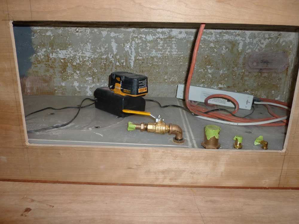
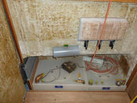
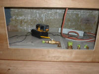
Temporarily installing the engine's remote coolant tank
on its new mounting studs in the pilothouse, I prepared
to continue work on the longitudinal bulkhead. I
clamped the bulkhead in place and made a series of marks
and measurements as needed to determine where to cut one
or more hatches, which would provide access to the
coolant tank and nearby fuel/water fill hose
connections. |
 |
One thing about design-on-the-fly is that relatively
simple things like cutting basic access holes tend to
take a long time. While cutting the hole is quick,
determining how large it should be, and where exactly it
should be located for best access, aesthetics, etc. can
consume abundant time.
Complicating the layout here was the yet-to-be-built
helm console, which required a space allowance (earlier
I'd traced the old console's shape on this bulkhead as a
rough guideline), and I also took into consideration the
position and clearance required for the helm and
steering wheel themselves, while running through the
back of my mind the whole time were other unknowns like
the final position of electrical panels, wire and hose
runs, and all the other things that might affect the end
utility of the boat.
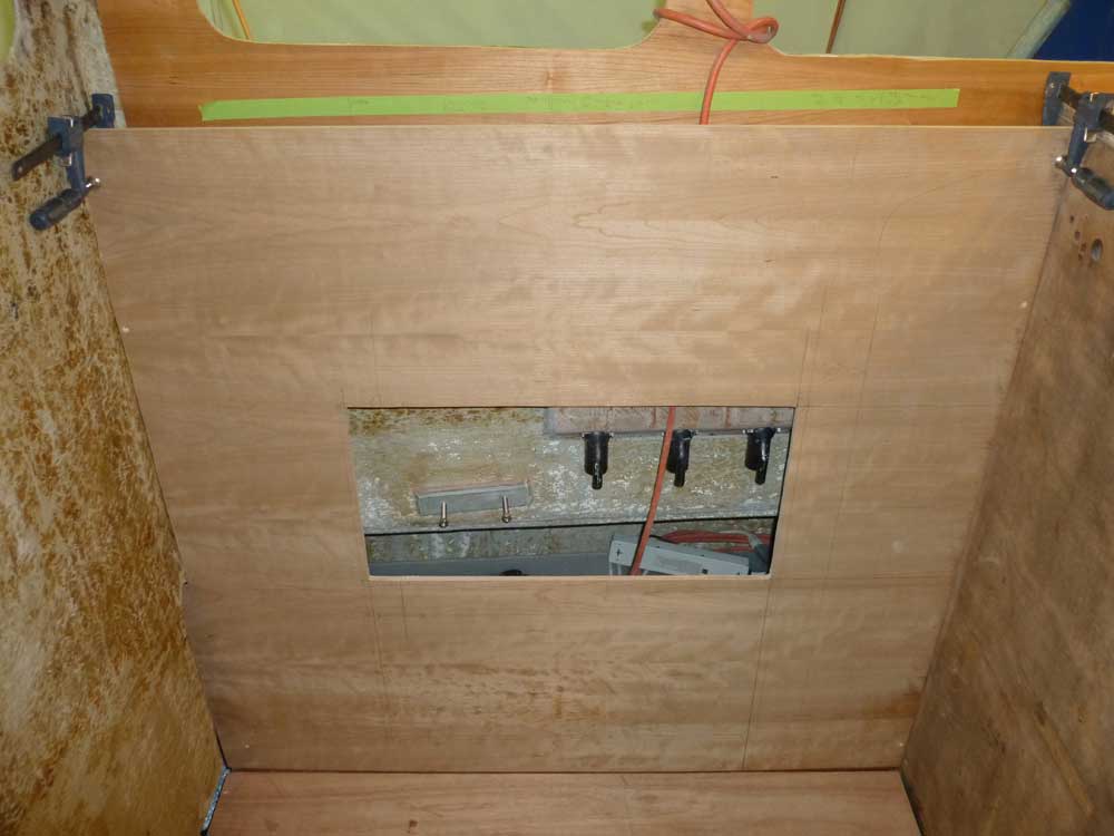
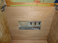
Eventually, I determined that a single large hatch would
give me the access I needed in the most simple and
attractive way, so after additional layout and
fine-tuning I cut out a large opening, but intentionally
a bit smaller than my initial thoughts; it'd be easy to
enlarge the opening if needed, but I had to start
somewhere. |
 |
Upon test-fitting the bulkhead with its new opening, I
found, not unexpectedly, that the aft end of the opening
didn't quite clear the coolant tank. So I enlarged
the opening by 2" at the aft end, which turned out well
since this made the opening symmetrical in relation to
the overall length of the panel (though when the helm
console was installed, this wouldn't matter). |
 |
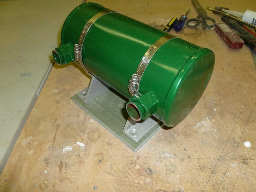
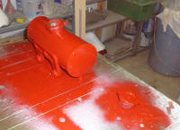
Meanwhile, I removed the coolant tank and brought it to
the paint room for some red paint to match the engine. |
 |
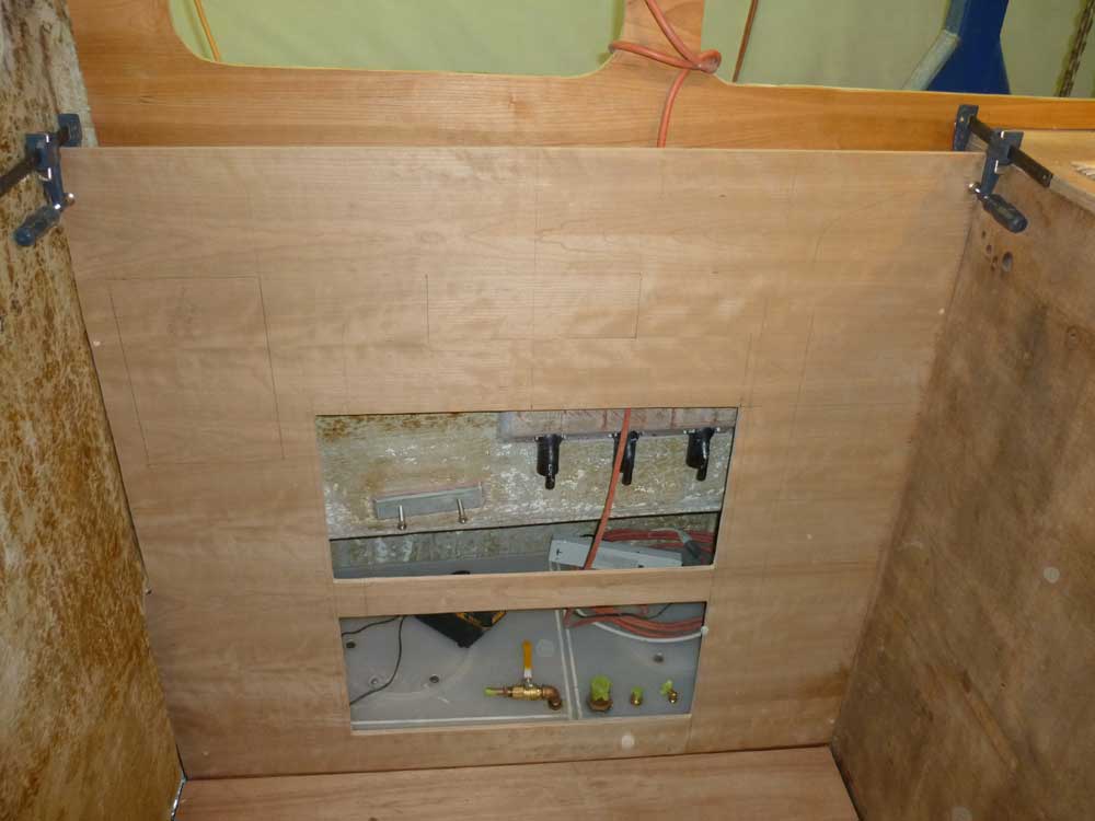
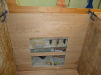
Next, I laid out and cut a similar opening near the
bottom of the bulkhead, which would provide access to
the tankage connections and everything else in the
locker. I made the opening as large as I could,
but kept it in line with the opening above.
Thinking of other ways to better utilize the space
behind this bulkhead, I laid out--but didn't cut--two
possible openings for recessed catch-all bins to hold
the detritus of daily life and other essentials. I
wasn't yet sure about these, so I left final decisions
for later. |
 |
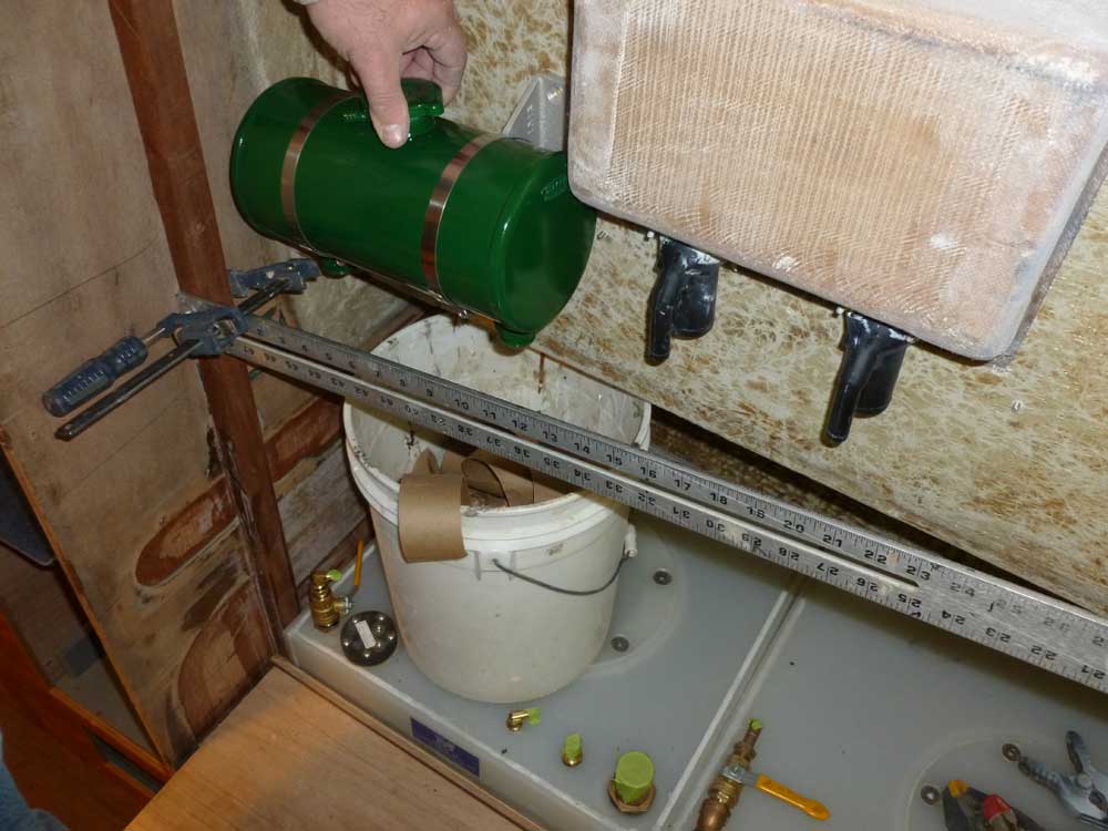
Now I moved on to the starboard bulkhead, which would
have its own--and similar--requirements. Once
more, the whole layout of this bulkhead depended first
upon the location of yet another expansion tank, this
one for the heating system itself.
Space constraints required that this tank be located to
starboard, where there was a bit more room because of a
shorter tankage fill recess (only two fills on
starboard, versus three to port), and, thanks to a quirk
of the boat's original construction, enhanced by a minor
layout mistake of my own, more space behind the bulkhead
and the pilothouse itself.
Clamping the tank to its supplied mounts (I'd painted
the tank earlier), I held it in position behind a
clamped-in metal ruler that simulated the position of
the bulkhead, and determined where the tank needed to
go. In this case, it only fit towards the forward
end of the space, but that was fine. |
 |
I began preparations to build a similar mounting block
and studs, as with the port tank, but left the bulk of
the construction--and eventual installation--till
another day. |
 |
| |
Total Time Today: 4 hours
|
<
Previous |
Next > |
|
|