Project Log: Sunday, August 12, 2012
I'd hoped to wrap up the diesel boiler's exhaust and
intake systems, but was unable to. Since the
exhaust line pretty much dictated where and how the
intake line needed to run, and since proper installation
of the exhaust was crucial to the heater in terms of
performance and safety, I needed to dictate its route
first.
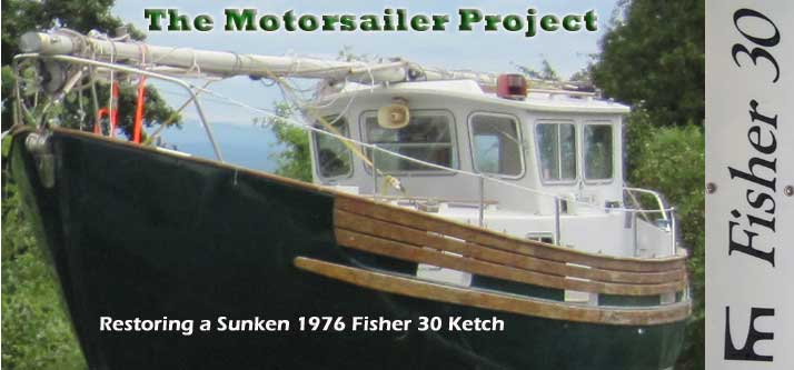
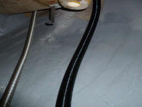
To begin, I attached one end of the exhaust flex pipe to
the new fitting in the hull, temporarily securing it
with a clamp. I led the remaining length of pipe
down into the engine room, where I'd figure out the rest
of its run. |
 |
The space aft of the engine on the port side was full of
plumbing hoses, and was generally difficult to access
thanks to tight clearance and, perhaps worse, the steep
angle of the hull in this area, which meant that even
once I shoehorned myself in I tended to slide out, and
it was impossible to keep tools, fasteners, or equipment
close at hand, so of course any actions required in this
space took several times longer than they might in an
more convenient setting.
At the extent of my reach, I simulated the exhaust pipe
run past the bottom corner of the cockpit, just aft of
the scupper opening, and it became immediately obvious
that I'd need a standoff bracket here to hold the pipe
in position and also keep it away from the fiberglass.
This didn't pose an immediate problem, as I had
standoffs on hand, but there was nothing handy to screw
the standoff to; the cockpit deck above was solid glass
in this area, but too thin to accept screws that would
hold the bracket.
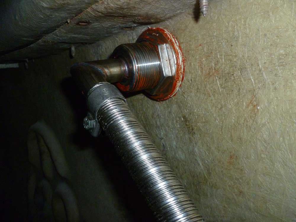
Instead, I secured a bracket with screws to a small
piece of prefabricated 1/2" thick fiberglass, then,
after cleaning the area, secured the block to the
underside of the deck with epoxy adhesive, and a dab of
hot glue to hold it while the epoxy cured. |
 |
This ended work on the exhaust and intake, since I
couldn't work with the standoff again till the adhesive
cured, and I needed to secure the exhaust there first
since doing so would dictate the remainder of the run
forward to the heater.
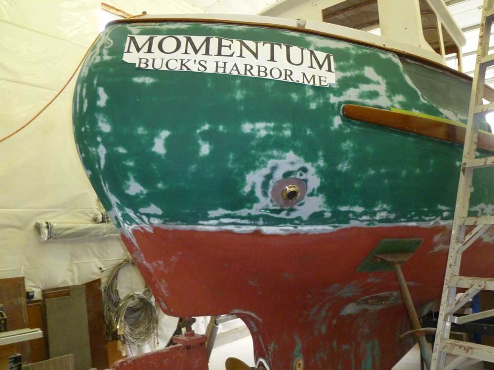
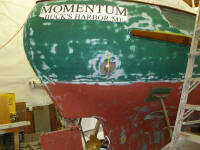
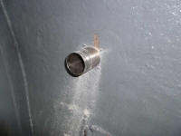
I moved on to the engine exhaust. Having had time
to consider my possible positioning of the exhaust
outlet fitting, I decided that my initial position was
unnecessarily high; it would have been annoying to come
alongside a dock, for example, since the outlet would
have probably been. above most floating dock heights
(not to mention higher than dinghy topsides, creating
the potential for embarrassing and annoying exhausting
into my or someone else's dinghy). There was
really no reason to have the outlet that high, and it
probably would have made hull staining a constant issue
as well, in spite of the drip flange built into the
outlet.
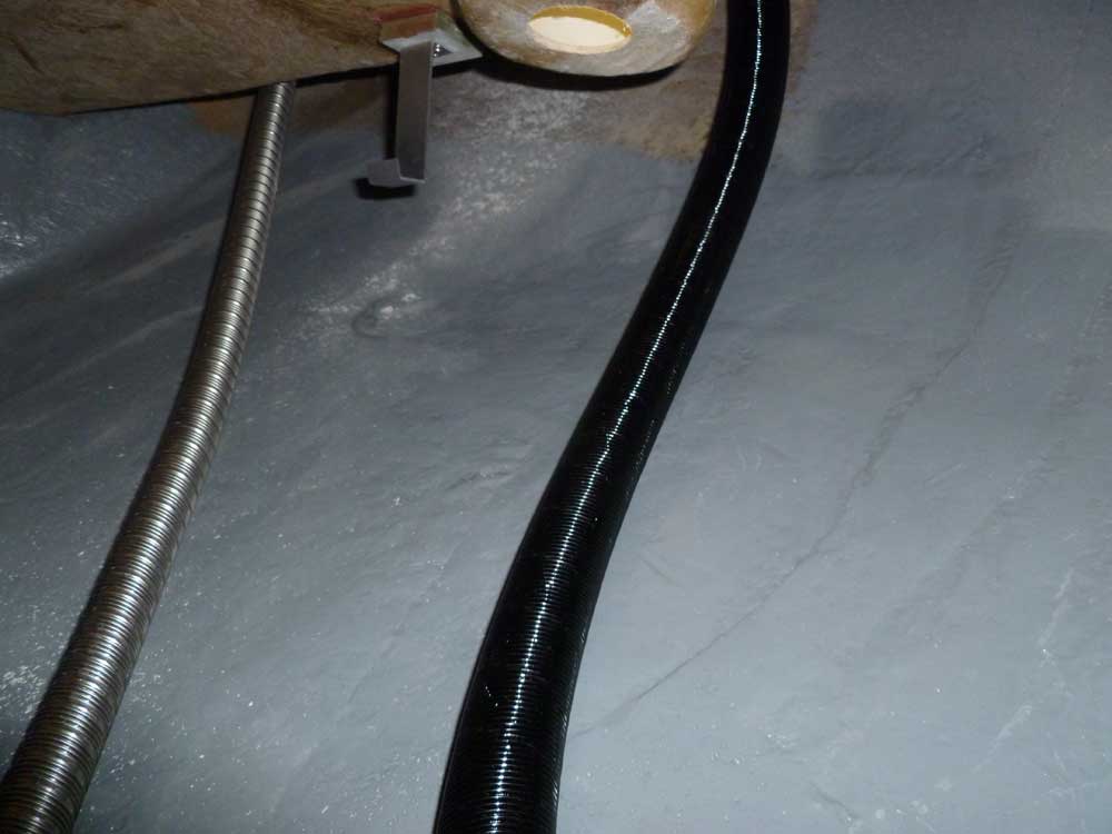
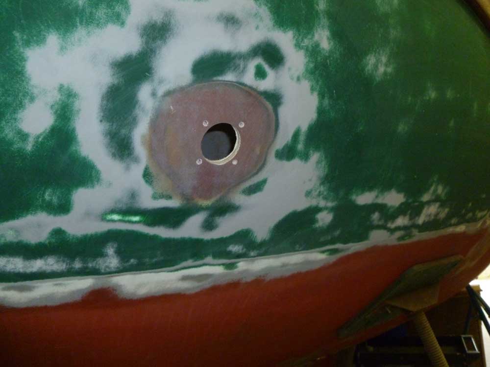
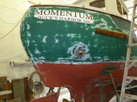
Instead moved it down the hull a bit to the spot where
the old bilge pump outlet had been originally installed
(since patched). This location was still well
above the waterline (and about 12" higher than the
original location, which was closer to amidships), but
the exhaust would discharge at a more convenient level
that was likely to remain below docks and dinghy
topsides. Similarly, I didn't want the outlet
closer to the transom, where it might pose a problem for
dinghy operations. I never considered locating it
directly outboard of the engine room like the original,
which I felt was a terrible location. |
 |
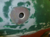
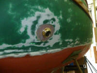
Satisfied with the location, I drilled a hole large
enough to accommodate the fitting, and dry-fit the
exhaust so I could drill and tap the hull for four
machine screws to secure it.
|
 |
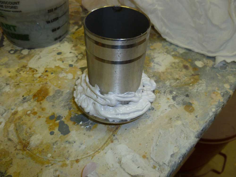
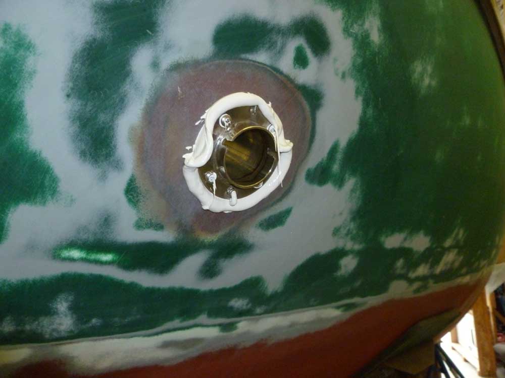
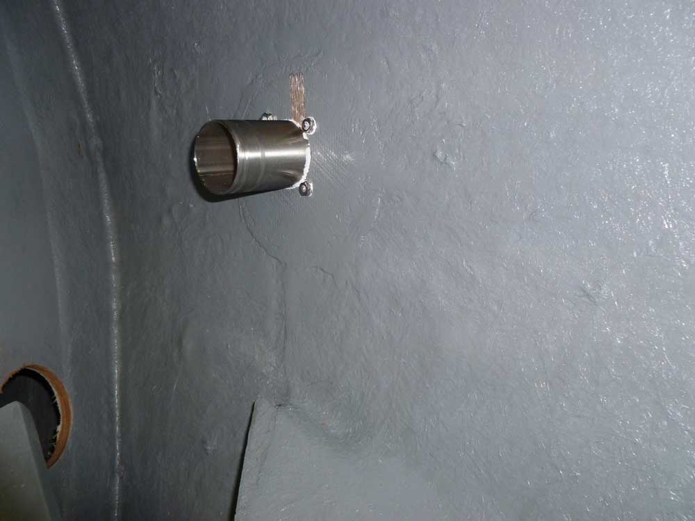
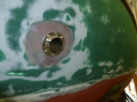
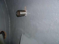
After preparing the fitting and opening, I installed the
fitting in a bed of sealant. I chose to install
the fitting now, before paint, because it would allow me
to continue critical systems installations in the
meantime, since painting was still a ways away.
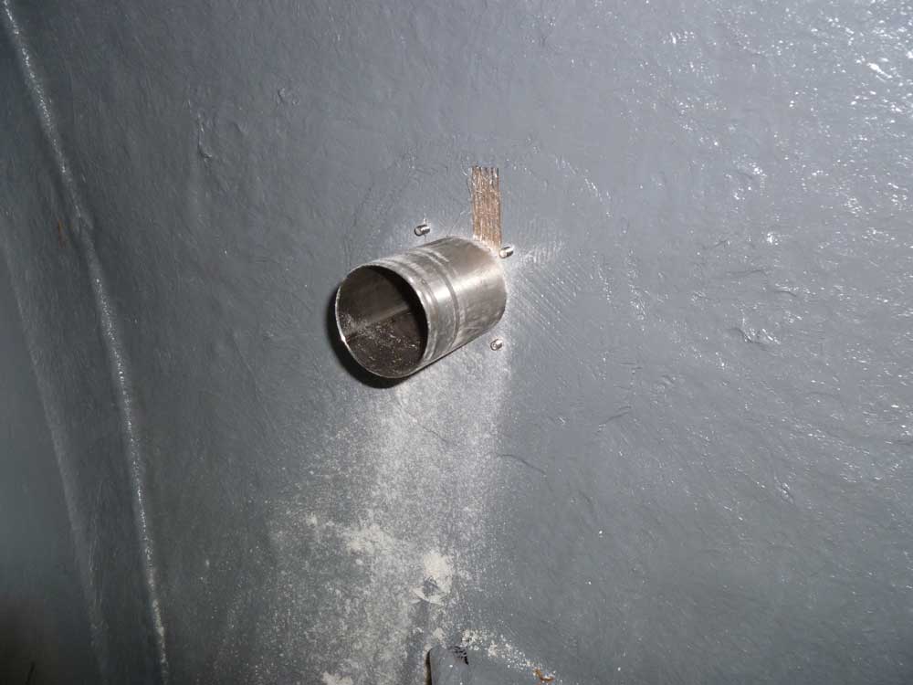
Inside, I added nuts and washers to the tapped machine
screws for good measure. For now, I reinstalled
the outer covering flange, which held the little flapper
check valve in place and covered the fasteners, but I'd
remove this later before painting. |


 |
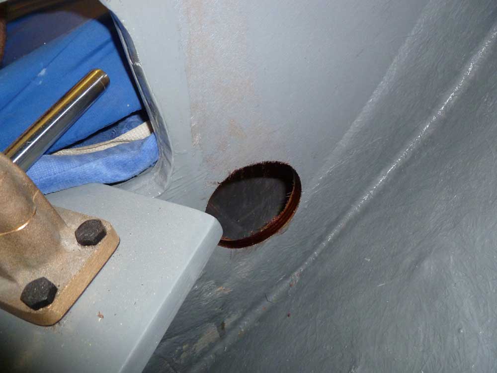
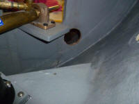
To get the exhaust from the engine to the outlet, I
needed another hole in the aft bulkhead. I drilled
a 3-1/2" hole through the plywood, just above the
tabbing and just below the level of the cockpit deck, to
provide access for the 2" ID exhaust (2-1/2" OD), with
room for chafe gear. Later, I'd lead the hose
through here and create a high loop up inside the
coaming before attaching the hose to the exhaust outlet.
To round out the work, I applied epoxy resin to the
freshly cut plywood bulkhead to seal the opening. |
 |
| |
| |
Total Time Today: 2.75 hours
|
<
Previous | Next > |
|
|