Project Log: Friday, August 17, 2012
Having completed various preliminary steps during the
last work sessions, now I could proceed and complete the
exhaust and intake runs for the diesel heater.
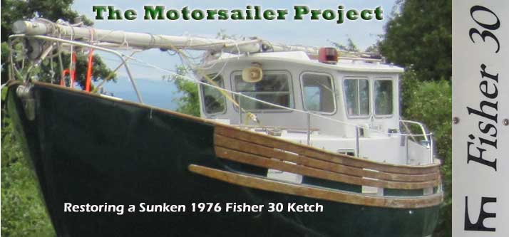
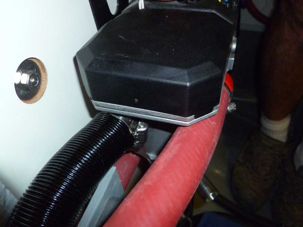
I began with the intake, to get it out of the way and
because it was straightforward. I secured the
intake hose up behind the cockpit well molding to a wire
tie mount that I'd installed earlier, then led the hose
through my chosen route to the heater itself, cutting
the hose as needed. Access to the intake fitting
on the heater was tight, but possible. To
help hold the intake line clear of some nearby
obstructions, I secured it to another wire tie mount
near the heater. |
 |
Next, I led the exhaust piping to the heater, and
determined its final length, which I marked on the pipe.
I left a little extra to be safe. Then, I removed
the pipe from where I'd temporarily clamped it to the
outlet fitting in the hull, and brought it down to the
shop so I could cut off the excess length.
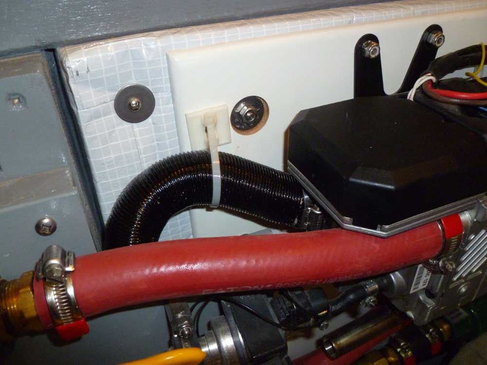
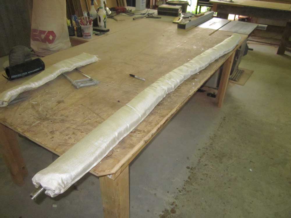
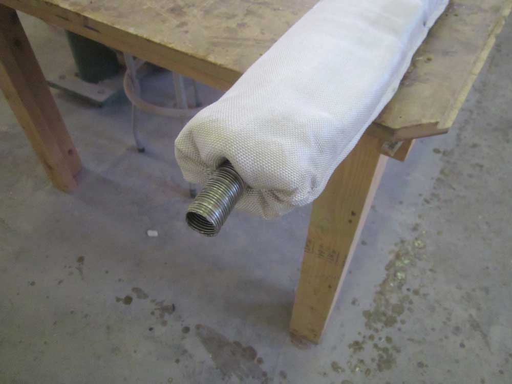
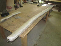
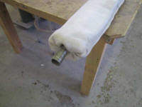
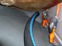
With the exhaust flex pipe cut as needed, I prepared a
length of insulating sock to pull over the pipe, and
pre-installed it, tucking in the ends as needed. |
 |
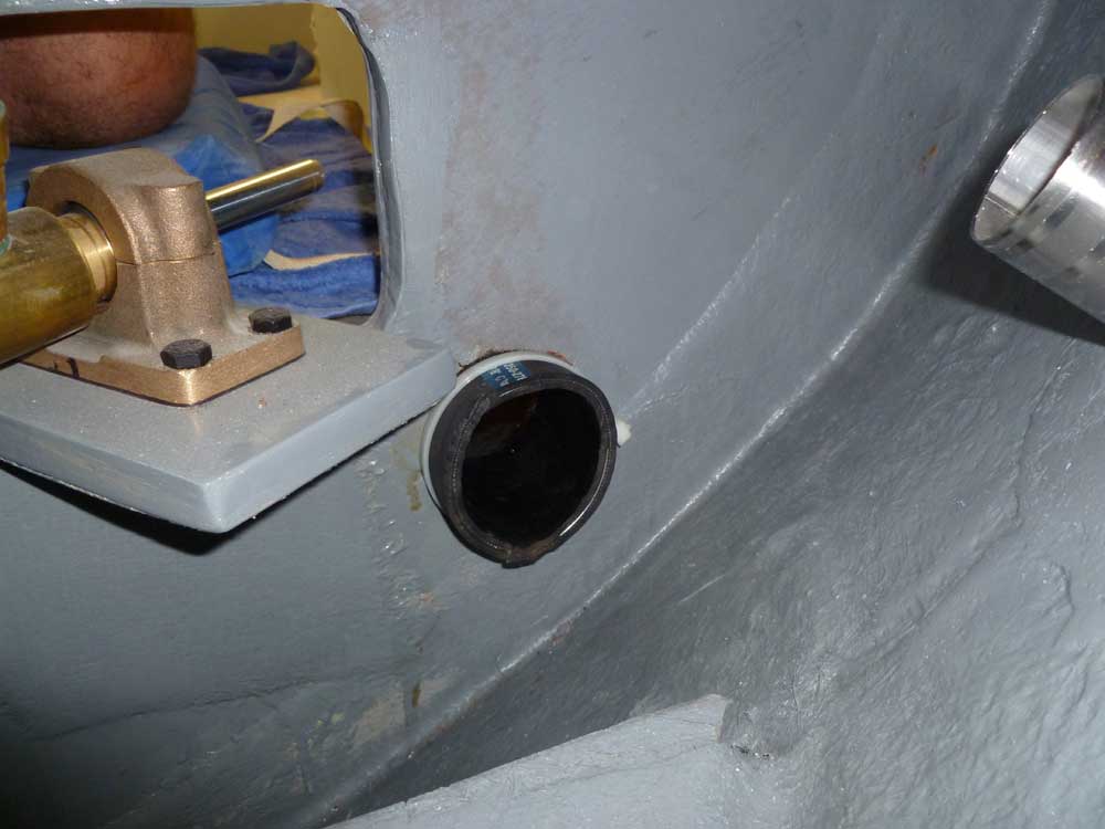
Bringing the arrangement back to the boat, I fed it down
through the inspection plate opening in the cockpit, and
double-checked the fit to ensure the pipe was the
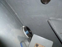
correct length. Since it looked OK, I continued
and applied more of the Ultra Copper RTV sealant to the
connection at the hull, through the cockpit deck plate,
and secured that end of the exhaust permanently.
The insulating sock ended just shy of the hull fitting
by design and instruction, to allow proper heat
dispersion through the double-walled fitting. |

 |
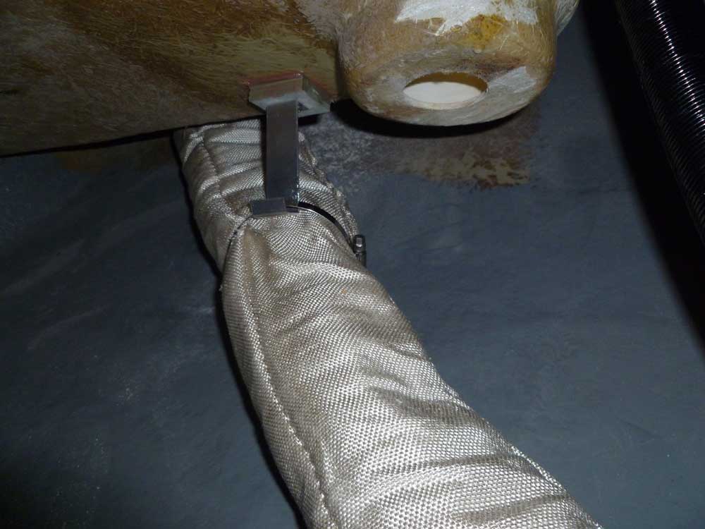
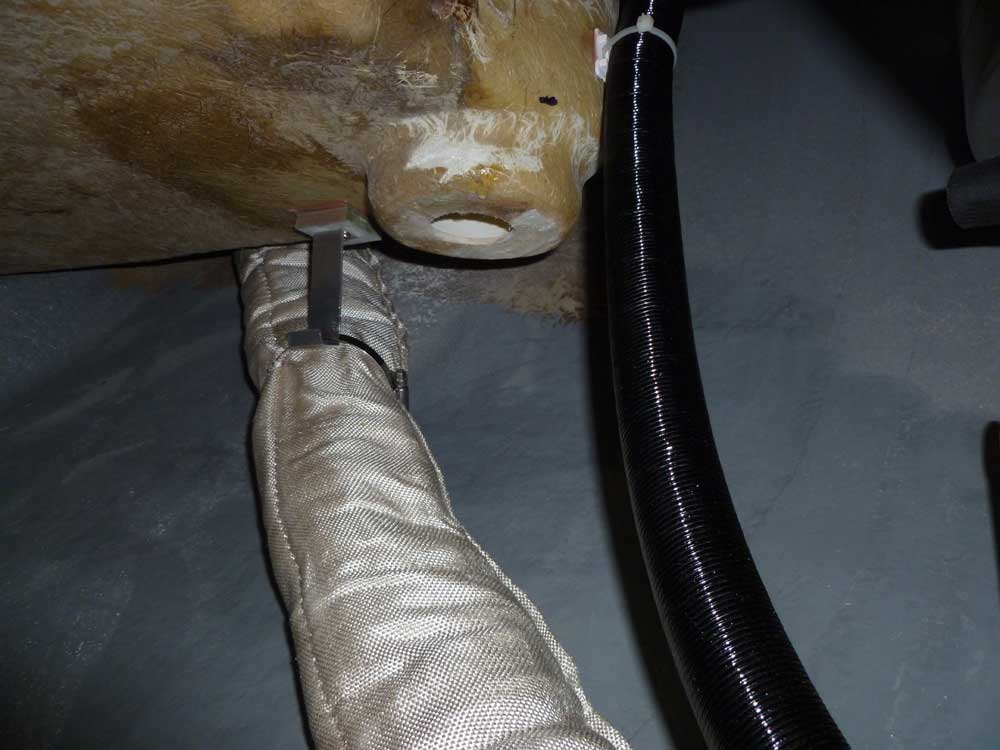
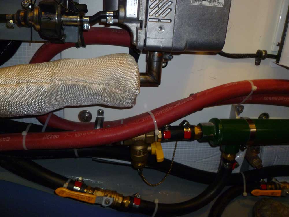
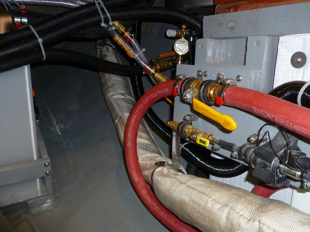
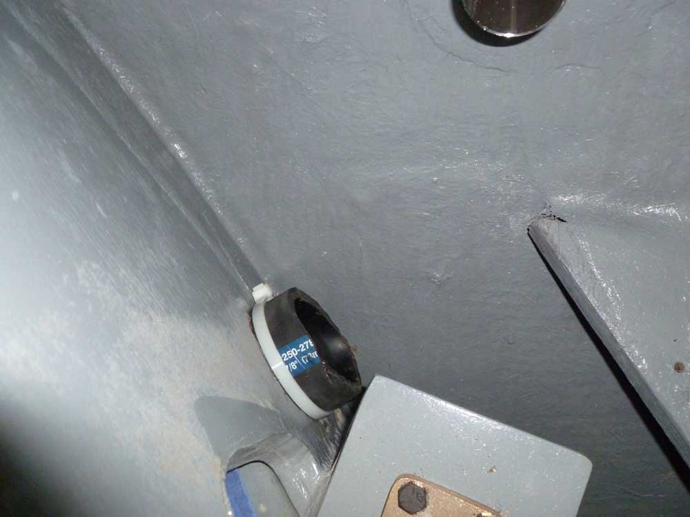
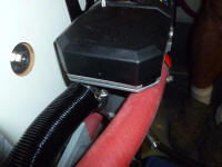
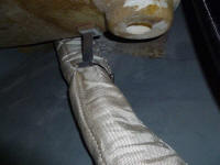
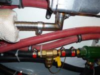
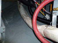
Down once again in my cozy space abaft the engine, I
secured the exhaust to the standoff fitting I'd
installed earlier, using a large hose clamp to more or
less hang the exhaust from the fitting. This held
the insulated exhaust pipe away from the cockpit and
hull, and helped direct it towards the heater itself.
|
 |
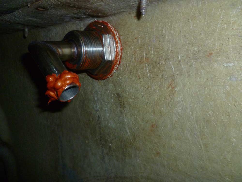
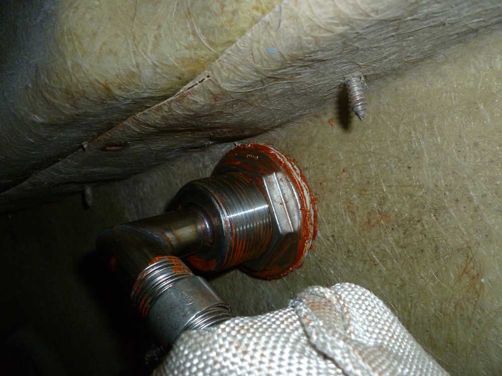
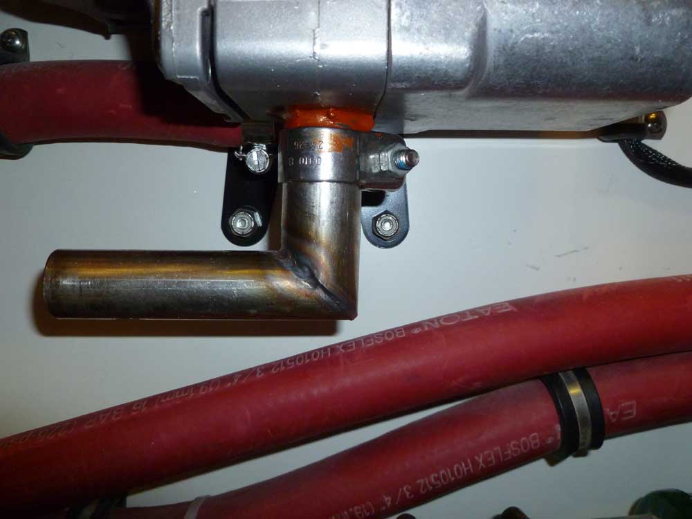
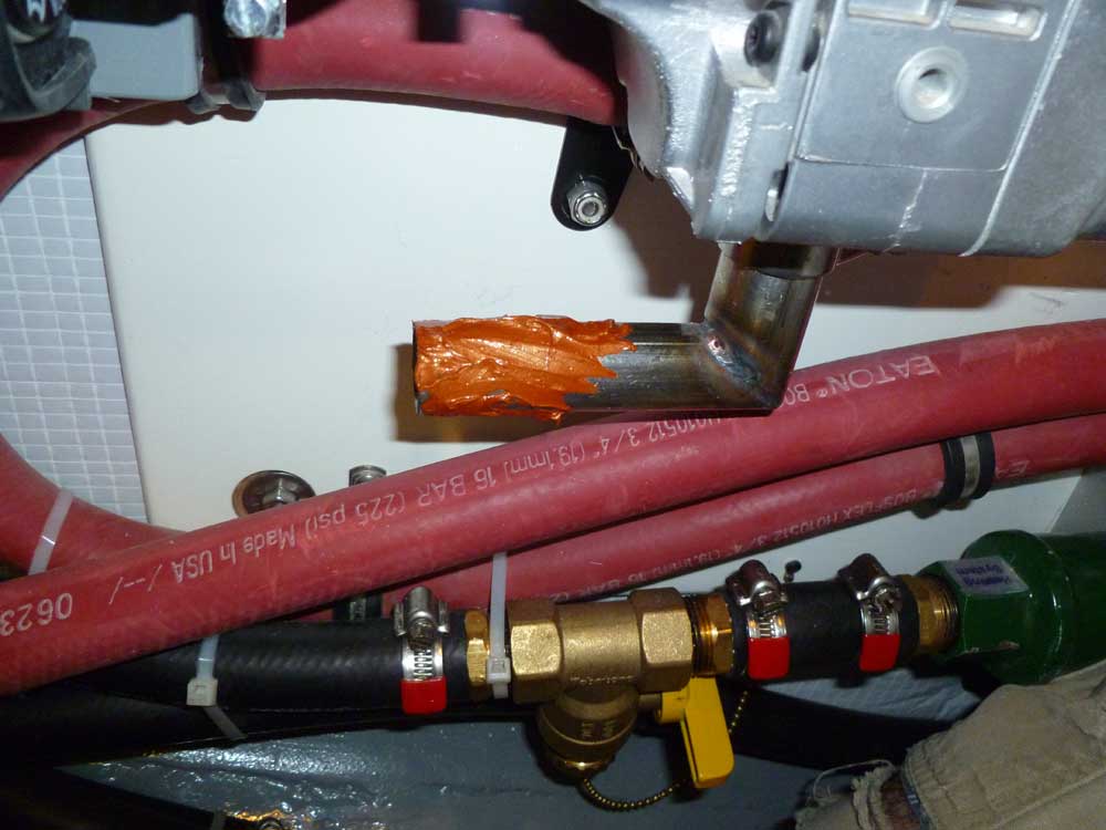
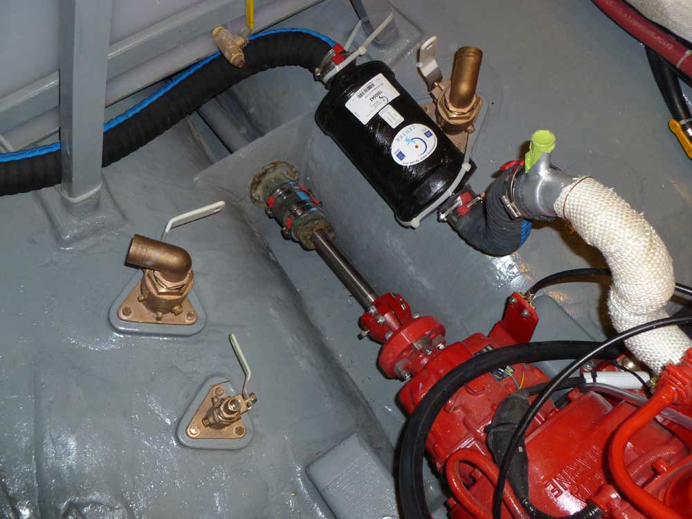
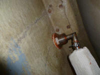
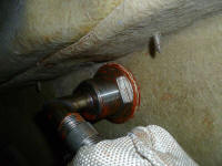
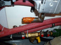
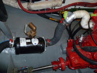
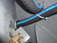
After a final check of the piping length, I removed the
90° outlet fitting from the heater and applied more of
the high-heat sealant, then reinstalled it permanently. |
 |
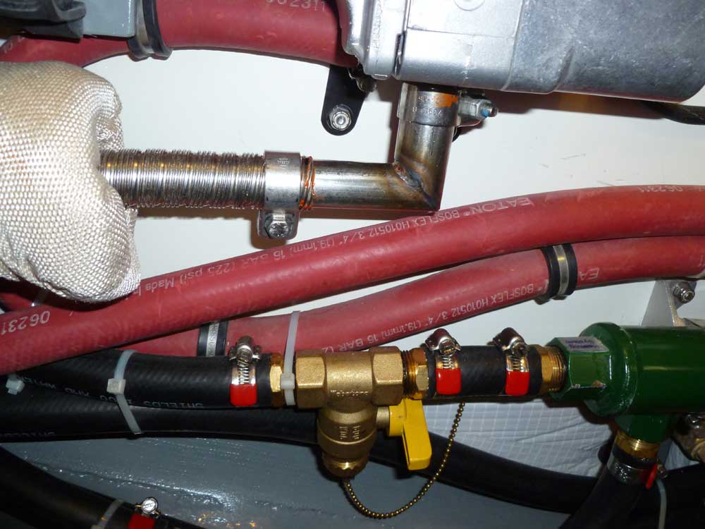
Finally, I sealed the exhaust pipe connection, and
secured the flex pipe in place. Although there was
plenty of clamping space, I'd hoped to pull the flex
pipe further onto the outlet fitting, but this was as
far as it would go. |
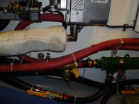 |
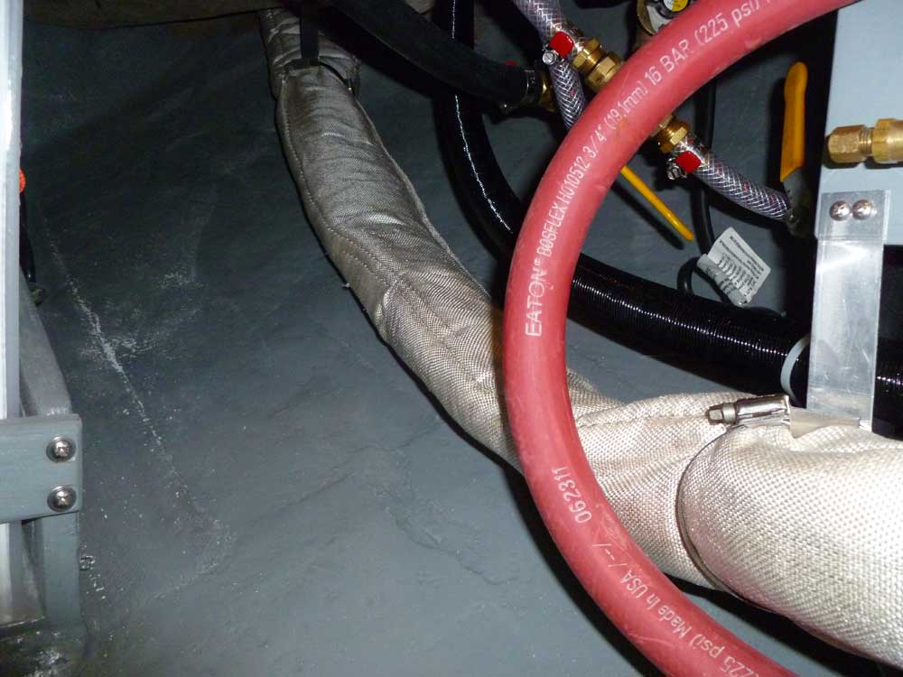
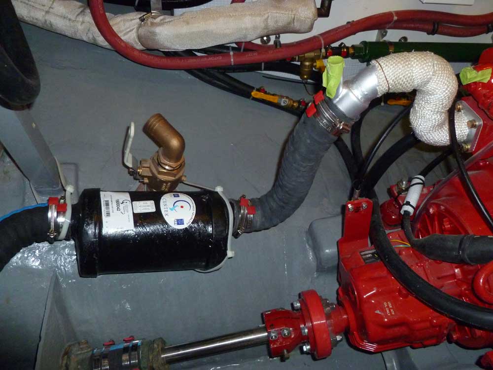
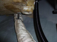
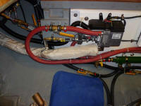
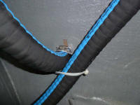
Now that the whole arrangement was in place, I found a
need to install one additional standoff, just a bit aft
of the heater beneath the fuel filter and pump for the
heater. Here, I straightened out the mounting
flange of the standoff so I could hang it straight down,
and secured it to a fiberglass plate I'd installed
earlier which held the fuel system for the heater.
This held the exhaust a safe distance from several
nearby installations. |
 |
With that, the bulk of the work surrounding the heating
system was finally complete. All that remained
were various wiring tasks, which I'd complete sometime
later. Quite a complicated little system, but I
knew that going in.
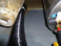
Next, I turned to the engine exhaust. To begin, I
cut a length of 2-7/8" hose to fit through my bulkhead
opening and act as chafe protection for the 2" exhaust
hose. This turned out to be a perfect fit and
actually a bit tighter than I'd anticipated. |

 |
Sometime earlier, I'd mocked up the general arrangement
of the exhaust and waterlift in the engine room, so
completing the exhaust at this point was just a matter
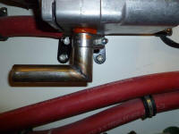
of course. Running a 12' length of 2" corrugated
exhaust hose through from the outside, I connected the
end to the waterlift outlet, then secured a
previously-cut length from the waterlift to the engine
elbow.
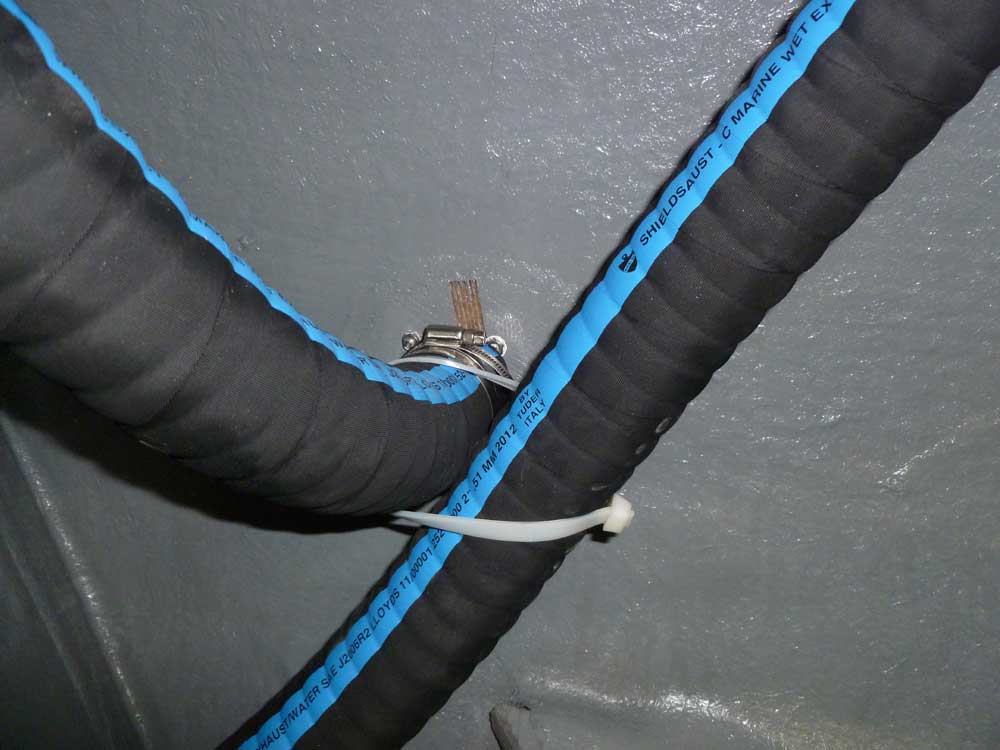
I was unhappy with how much excess clamp tail there was
on these clamps, but the exhaust hose OD landed in a
very awkward place where there wasn't a specific AWAB
clamp size that fit perfectly: the next size down
was far too small, and the only size that fit featured a
large clamping range that necessarily dictated longer
tails in this instance.
I secured the waterlift to nearby conveniences with
large cable ties. Later, I'd add some chafe gear
to the exhaust hose in a couple areas, but I didn't have
anything on hand at the moment. |

 |
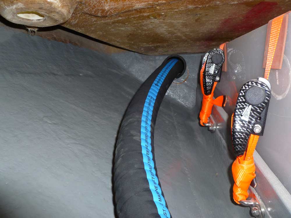
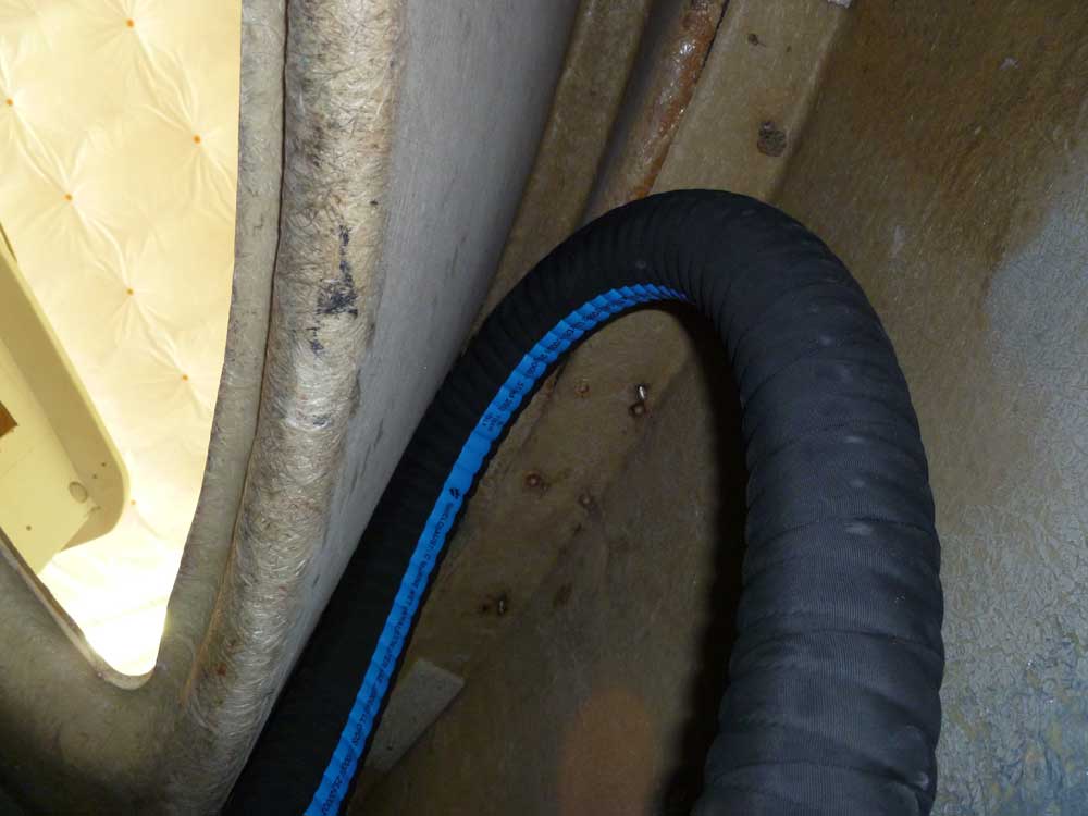
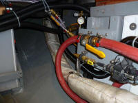
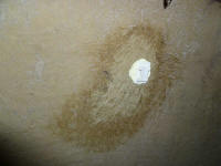
Back in the after steering room, I used the remaining
length of hose to form a high loop that extended nearly
to the underside of the gunwale within the raw space
behind the cockpit coaming, then secured the end to the
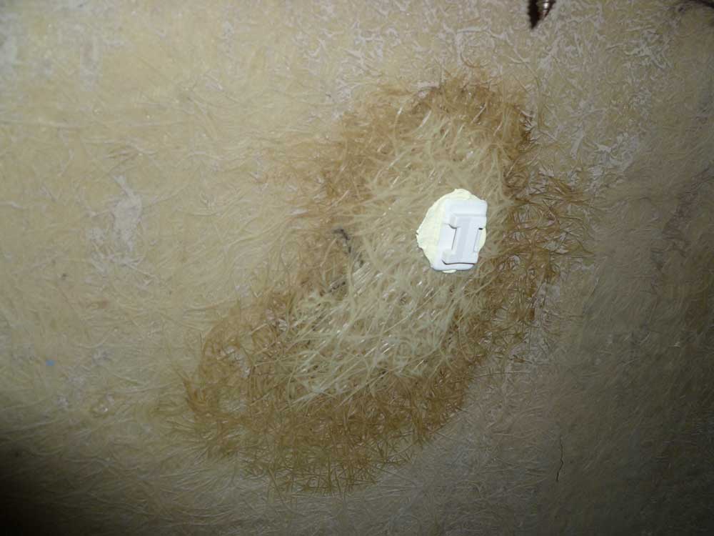
hull exhaust outlet. Reaching through a nearby
access hole, I cleaned a small section of the bare hull
and installed a wire tie mount, which I left to cure
overnight but would eventually use to secure the top
portion of the exhaust loop. This high loop would
prevent nuisance water from flowing in the exhaust
outlet and down to the engine, as the top of the loop
would always be well above the waterline. |

 |
| |
Total Time Today: 3 hours
|
<
Previous | Next > |
|
|