Project Log: Wednesday, January 4, 2012
I continued work on the rough helm area mockup.
Having determined what I needed to with the helm pump
and wheel yesterday, I removed them from the mockup to
avoid damage and because the weight of the helm pump
made the mockup unstable.
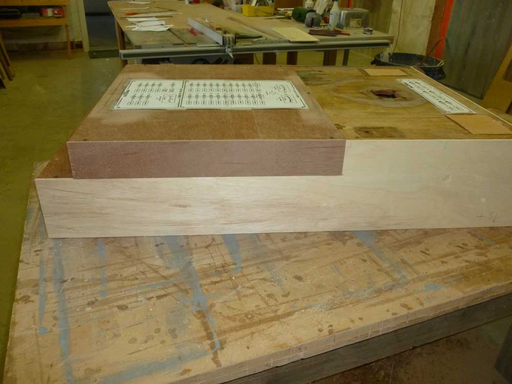
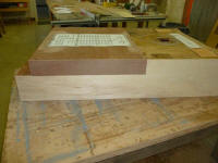
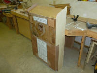
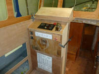
I decided I wanted more room in the lower portion of the
console, behind the electrical panel. With the
knowledge that the steering wheel wasn't going to impact
the operation of the panel or my intended hinged cover,
I didn't see much reason for the lower portion of the
console to be set back several inches, so I extended the
sides with additional plywood, cleats, and glue to bring
the lower portion of the panel flush with the upper
section. I left a 3" tall toekick at the
bottom, but quickly realized this wasn't tall enough, so
I knew I'd have to make changes in the final
construction later. |
 |
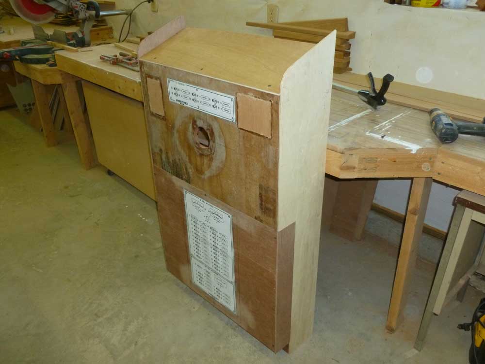
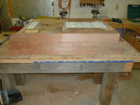
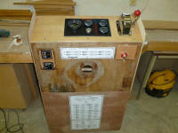
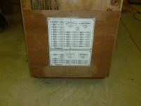
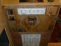
Meanwhile, I spent a few minutes printing out some
full-sized drawings of the electrical panels I was
thinking of, to better represent them visually as I
worked through the console design. The large main
panel still fit in the space, but was now impinging on
the available length of the lower section more than I
wanted, particularly when I accounted for the recessed
frame that added nearly 1" all around.
Effectively, I'd shortened the lower section by 3", or
the height of the toekick, and now the length of this
panel was pretty tight in the remaining space For
the moment, I left things as they were, but sensed I'd
need to make a change in the service panel for a better
fit. |
 |
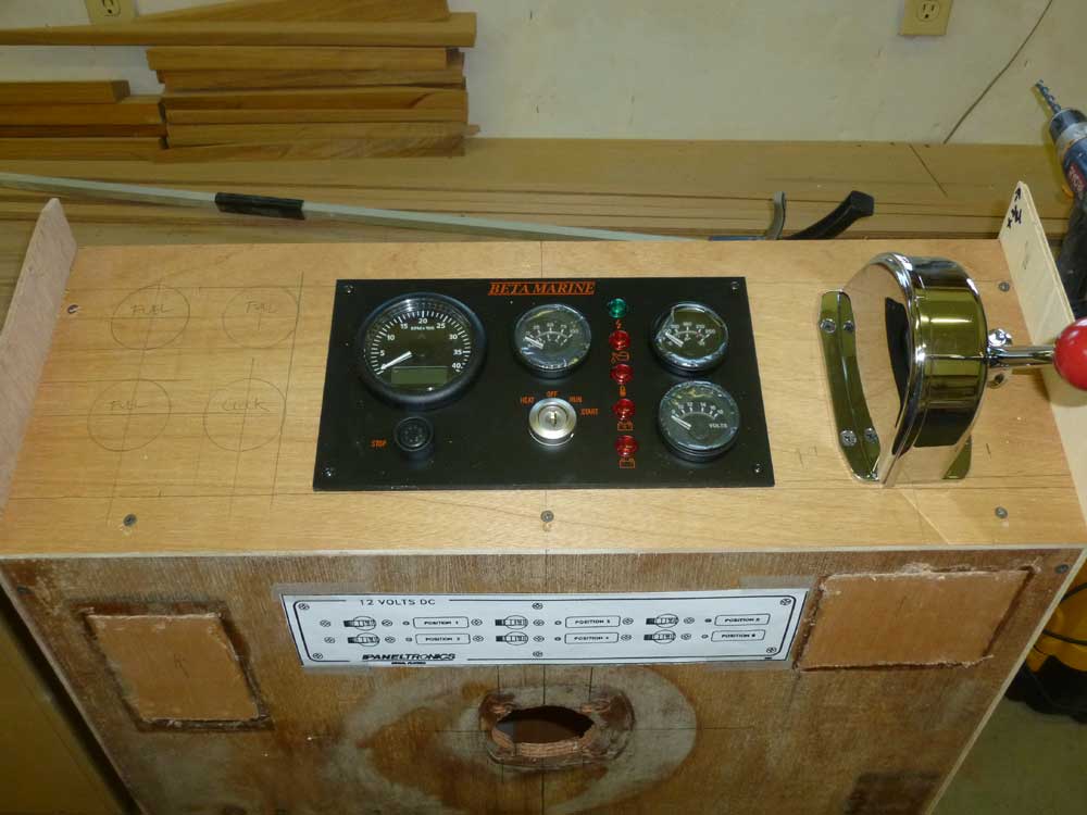
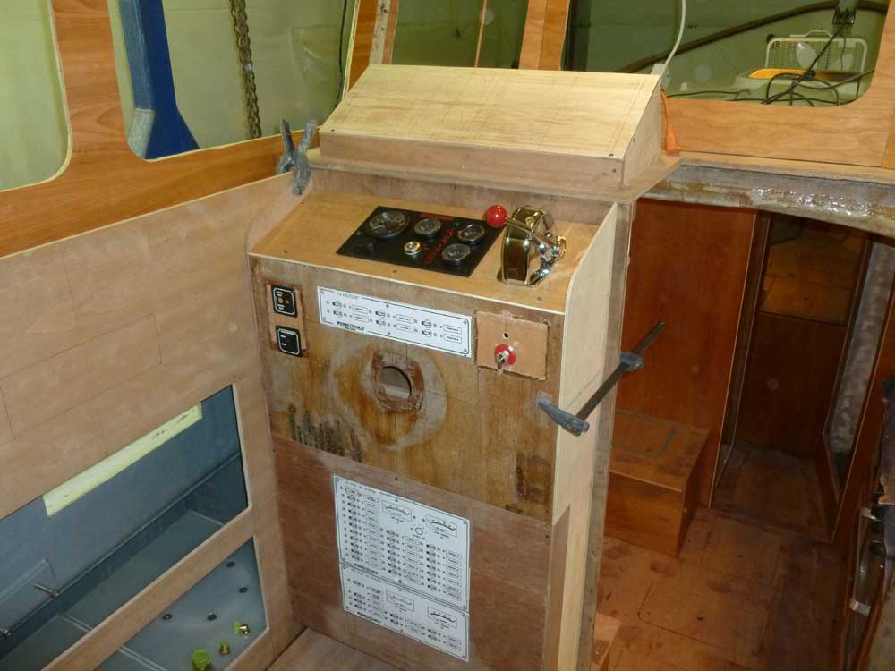
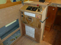
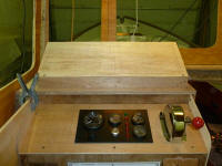
With the modifications to the box complete, I worked on
my initial layout for the planned installations on the
console--all subject to change throughout the process.
I located and installed the engine control, engine gauge
panel, and fuel gauges in the angled top panel of the
console. I debated the merits of recessing the
engine panel, something I still might end up doing in a
later version of the mockup or actual construction, but
for the moment I installed it on top in the normal way. |
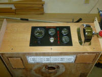 |
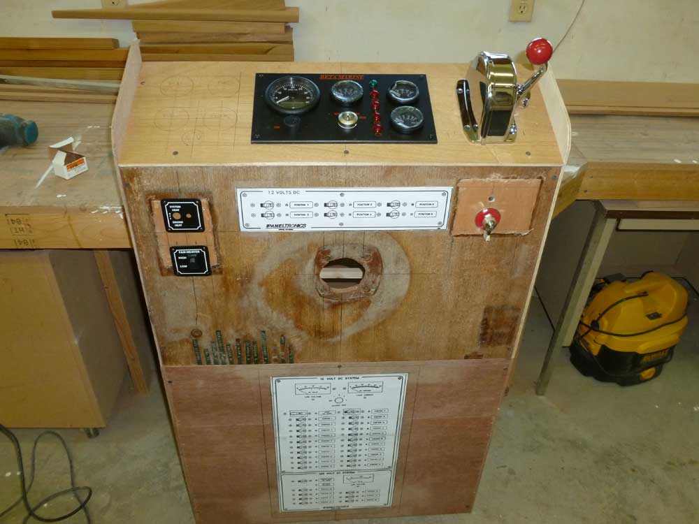
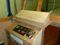
Then, in the front panel of the console, I installed
controls for the heating system and bilge pump. |
 |
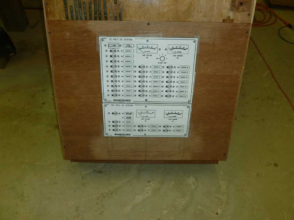
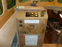
At this point, I decided to make a change in the
electrical panel. Knowing from my discussions with
the vendor that I could combine different panels in the
same enclosure, I selected a 24-position DC panel and
7-position AC panel that gave me roughly the same switch
capacity as my original choice (with three additional DC
breakers that I didn't really need), but were housed in
panels that were wider and shorter than my original
choice.
This had the unnecessary but still somehow satisfying
consequence of making the lower, main panel be the same
width as the small nav lights panel at the top edge of
the console. The shorter overall height was a much
better fit in the lower section of the console, and
would give me plenty of room for as large a toekick as I
wanted (though I wouldn't bother making the change on
the mockup). |
 |
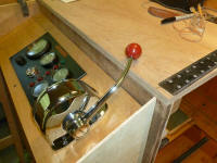
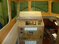
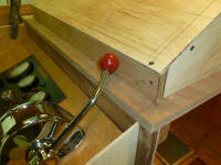
With the console up in the boat, I checked clearance for
the throttle lever. While it not-unexpectedly hit
the upper part of the pilothouse dashboard before
reaching its full travel, I didn't think it would travel
that far once cables were attached (and probably
wouldn't pose a practical problem if it did), but
nonetheless I considered the possibility of changing the
orientation somewhat to eliminate the issue if needed. |
 |
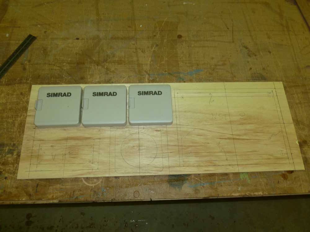
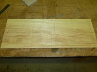
Navigation electronics would be flush-mounted in a
separate box, to be located on the dash itself, and this
was the next thing for me to mock up. After taking
a few measurements of the available space, I cut a 1/4"
scrap plywood panel to what I thought would be
appropriate dimensions for the space and for the
installations required, and laid out the positions of
the multi-function display (Simrad NSE-8), VHF radio
(Simrad), autopilot control head (Simrad AP24), and
sailing instruments (Simrad). |
 |
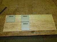
In this initial configuration, there were two possible
orientations for the three identically-sized square
instrument heads. My first thought had been to
stack two of them vertically in the space between the
large display to starboard and the VHF to port, with the
autopilot control head off on its own above the VHF.
This also left room for a few small installations like
USB ports and 12V outlets. |
 |
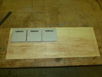
However, there was also just enough room to locate all
three control heads in a horizontal line across the top
of the panel space, and after due consideration I was
leaning towards this configuration. |
 |
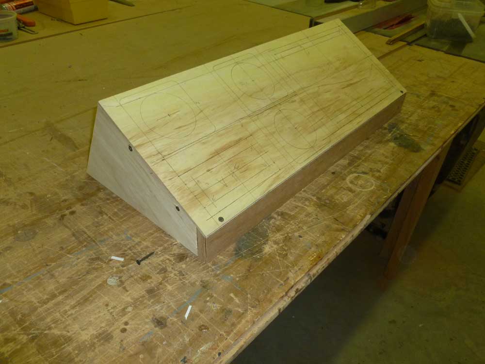
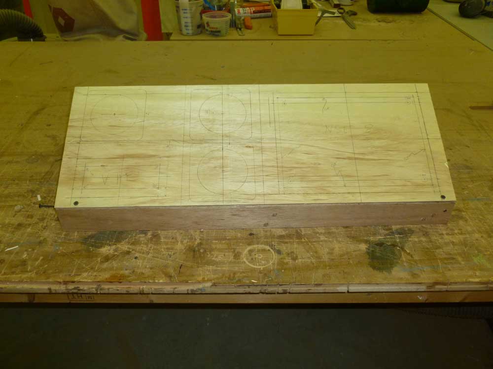
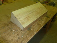
I more or less randomly selected a 30° angle for the
face of the electronics console, and built a basic box
beneath the plywood top to simulate this setup. I
started with a 2" tall vertical at the low end (aft) and
worked from there. |
 |
With the new box set up in place in the pilothouse, my
immediate thought was that the angle needed to be
steeper for easier access to and better viewing of the
NSE-8. I also felt that the 2" tall vertical was
too high, so for the next round I expected to make some
changes. The angle of the panel and its overall
height had to be balanced between usability (most
important), impact on forward views from the helm
(probably not a real issue no matter how I laid it out),
and overall aesthetics.
Before making any changes to the original configuration,
however, I'd probably cut the access holes and install
the actual electronics to see how it all felt with the
real units in place. |

 |
Finally, I checked the clearance of the throttle lever
with the box in its intended position. |
 |
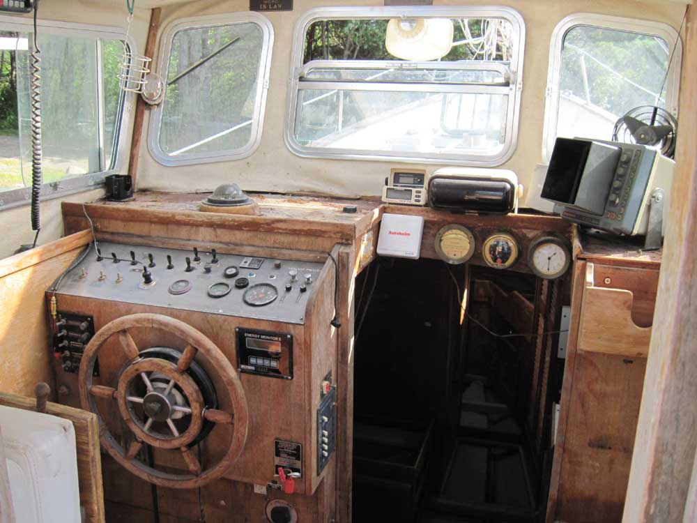
For ready reference, this is what the area looked like
when I got the boat. |
 |
Total Time Today: 6.5 hours
|
<
Previous | Next > |
|
|