Project Log: Friday, March 14, 2014
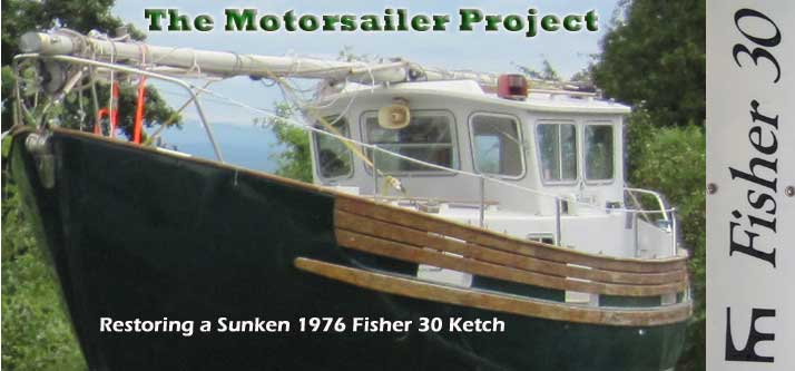
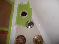
In the head, I decided to install the large waste pump,
seeing no reason not to get it out of the way.
Installation was straightforward since I'd already laid
out and prepared all the holes required. I used
1/4" machine screws with fender washers on the outside,
since operation of this pump would stress the bulkhead
and the pump's fastenings. Access to the pump
through the nearby access opening was excellent.
|
 |
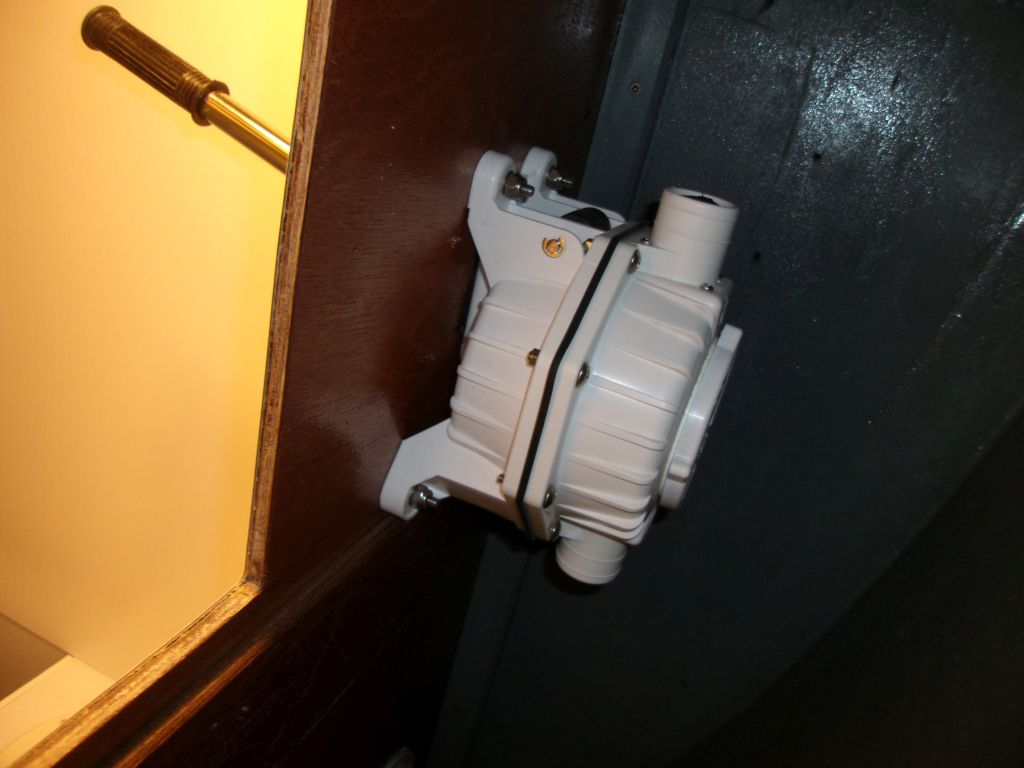
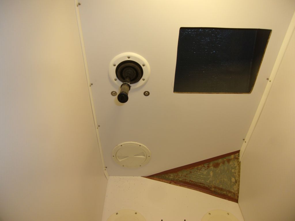
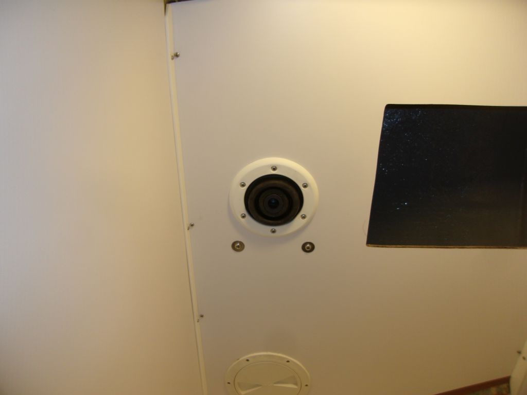
Included with the kit was a rubber bellows and trim
piece, which I installed over the pump handle from
outside. |
 |
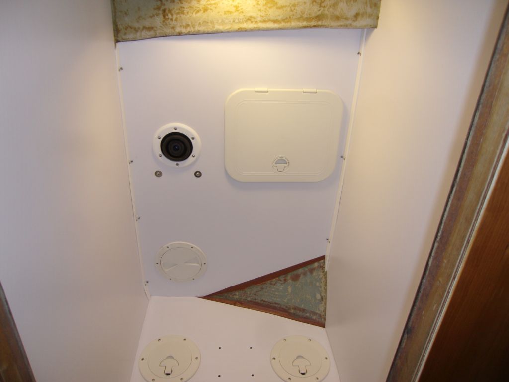
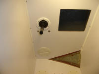
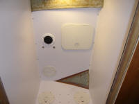
To get a sense of the finished space, and also to
temporarily "store" the unit till final installation, I
dry-installed the plastic access hatch in the panel with
a couple screws. I chose the latch-down
orientation because I thought it would be the most
water-resistant, with the hinges facing up. To
hold the hatch open, later I'd add some means of
securing it to the bulkhead above. |
 |
Other than seam caulk, paint, and final plumbing
installation, the head compartment was complete, and for
the moment I moved on to other tasks, starting with some
hardware installation on the foredeck.
To service the forward water tank, located beneath the
v-berth, I needed a tank fill nearby. Much
earlier, I'd purchased one that shared its appearance
with those back in the pilothouse, though for this one I
planned a separate (internal) tank vent rather than the
integral vents like those used back in the pilothouse.
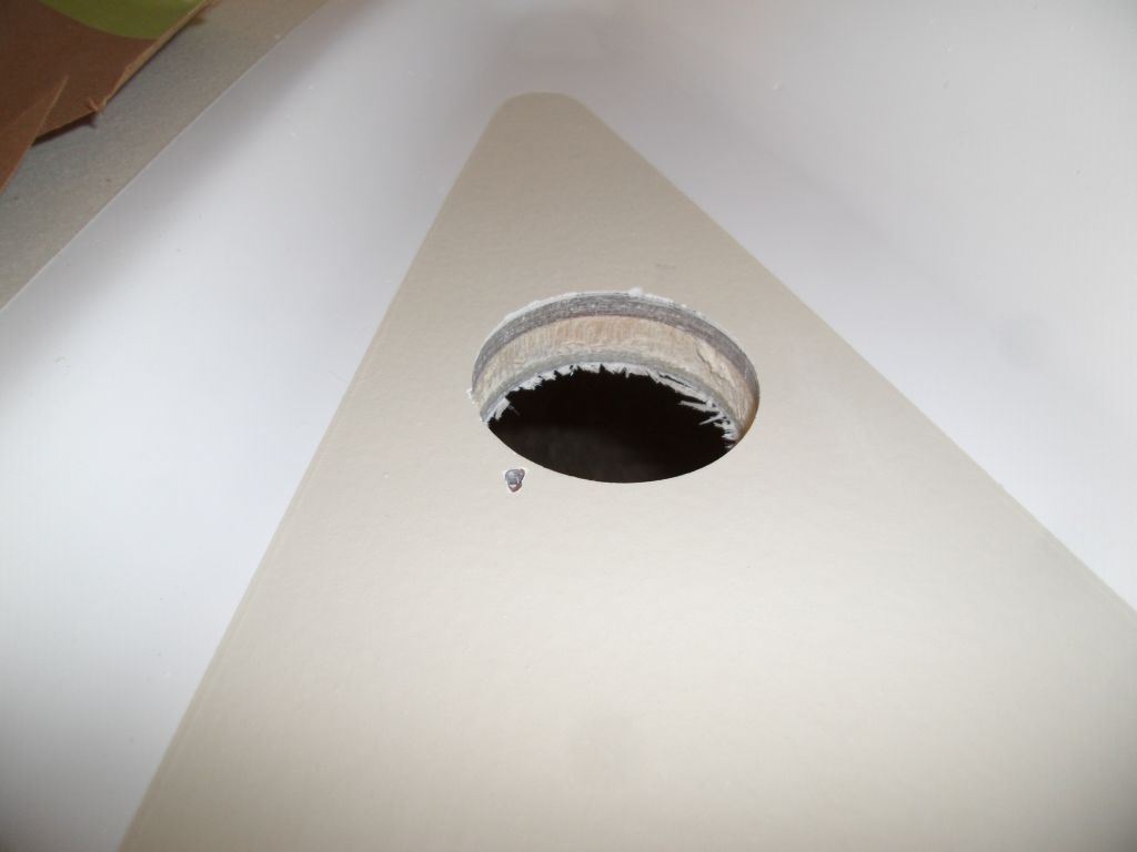
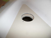
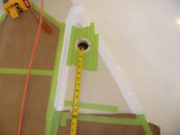
To locate the fill, I started belowdecks, and drilled a
small pilot hole through the center of the old tank
fill's location, which I'd patched during early stages
of the project. Back on deck, I found that the
pilot hole wasn't quite where I wanted the fitting to be
centered, so I adjusted slightly as needed before
drilling the large hole required, centered in the V
shape of the nonskid pattern. The pilot hole
worked out well as one of the three fastener holes
required. |
 |
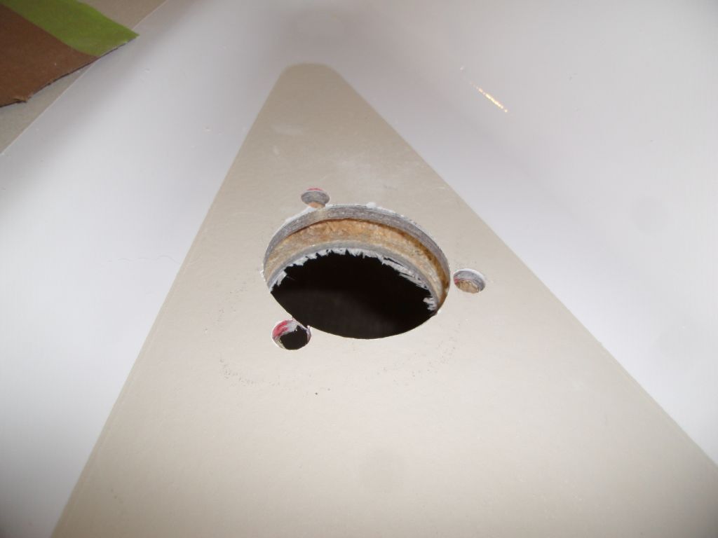
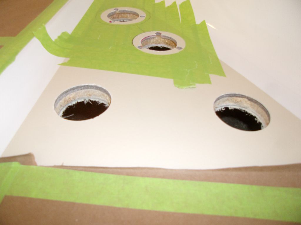
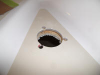
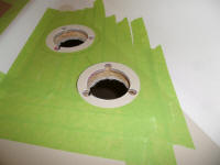
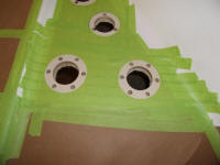
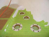
Next, in the usual way, I marked and overbored the three
fastener locations, removing core from these areas, and
also removed the coring from around the large hole
before masking around the opening and the mounting
flange of the tank fill itself. |
 |
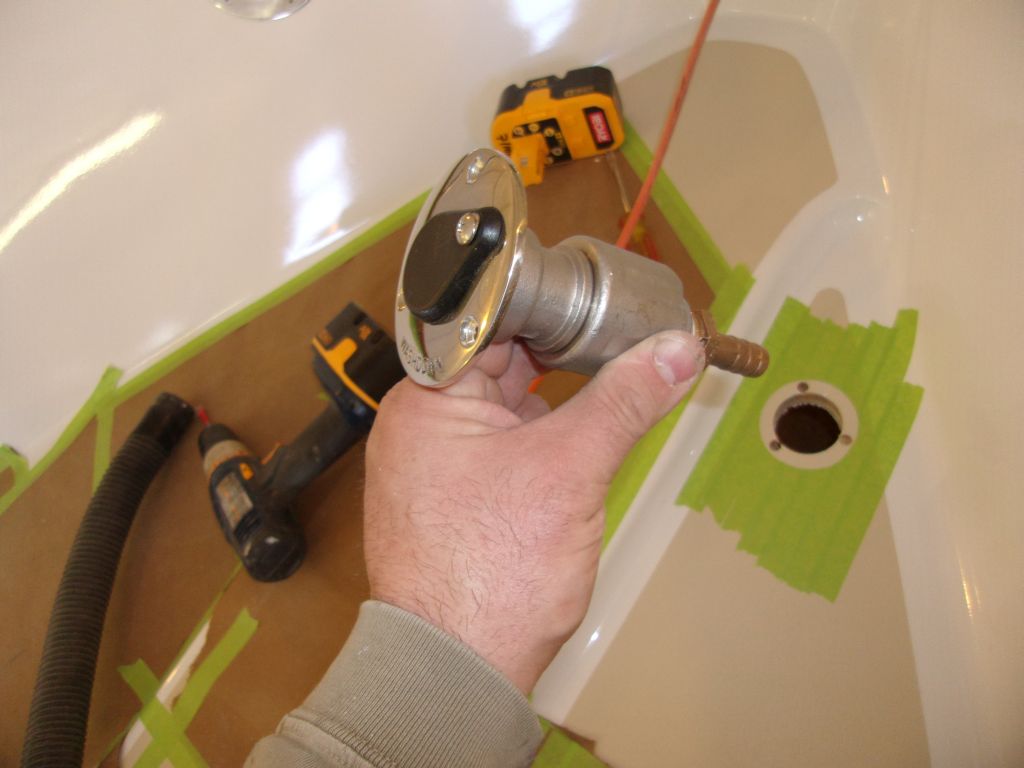
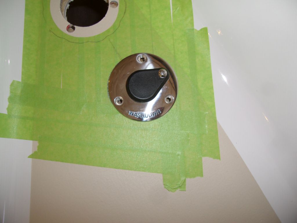
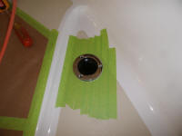
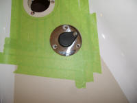
To service the eventual saltwater washdown pump, I found
an interesting flush fitting for the purpose, which
incorporated a spring-loaded mechanism and a special
hose adapter. To use the fitting, and access
water, one simply pushed the adapter into the fitting,
compressing the spring and allowing water flow.
Removing the adapter would stop the flow. No taps
needed, and the fitting had a clean profile. |
 |
I located the hole for this fitting just aft of the
water tank fill, and in line with it according to the
outboard edge of the nonskid pattern. I prepared
the mounting hole the same way, removing core from the
areas directly surrounding the opening and the
fasteners. |
 |
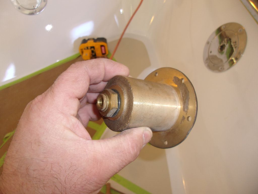
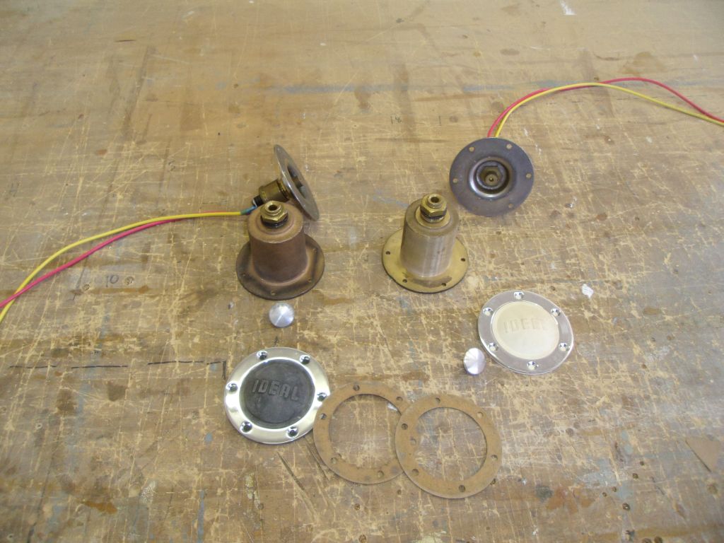
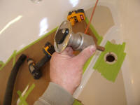
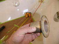
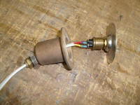
One of the reasons I selected an older Ideal Windlass
for my first personal foray into the world of windlasses
was stuff like this: these hefty bronze housings
that protected the wiring for the foot switches.
Things like this exude good design and engender high
confidence. These would mount to the switches from
belowdecks, allowing future access if needed.
Because their bolt patterns and mounting flanges were
the same as the switch plates themselves, I used these
for layout purposes since they were more convenient to
work with than the switches and their mounting plates
themselves. |
 |
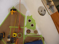
Belowdecks, I made a measurement from the water tank
fill to the chain locker bulkhead, so I could transfer
the bulkhead's position to the deck. I wanted the
foot switches to come through in the chain locker, where
the wiring would be hidden and protected. Allowing
plenty of extra room, I determined 10" to the bulkhead,
and made a mark on deck. |
 |
Striking a perpendicular line to the centerline of the
boat, approximated off the raised center portion of the
foredeck, I determined the positions for the two foot
switches. Once happy with the position, I marked
the centers of the holes with a pencil. |
 |
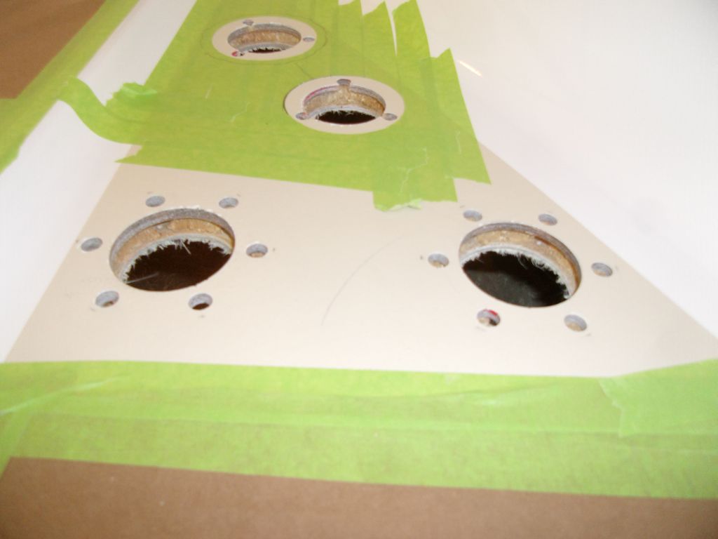
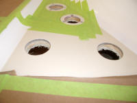
With a hole saw, I cut out the holes as needed, then
prepared them as with the other openings, removing core
and preparing the fastener locations before outlining
the mounting flanges with tape. |

 |
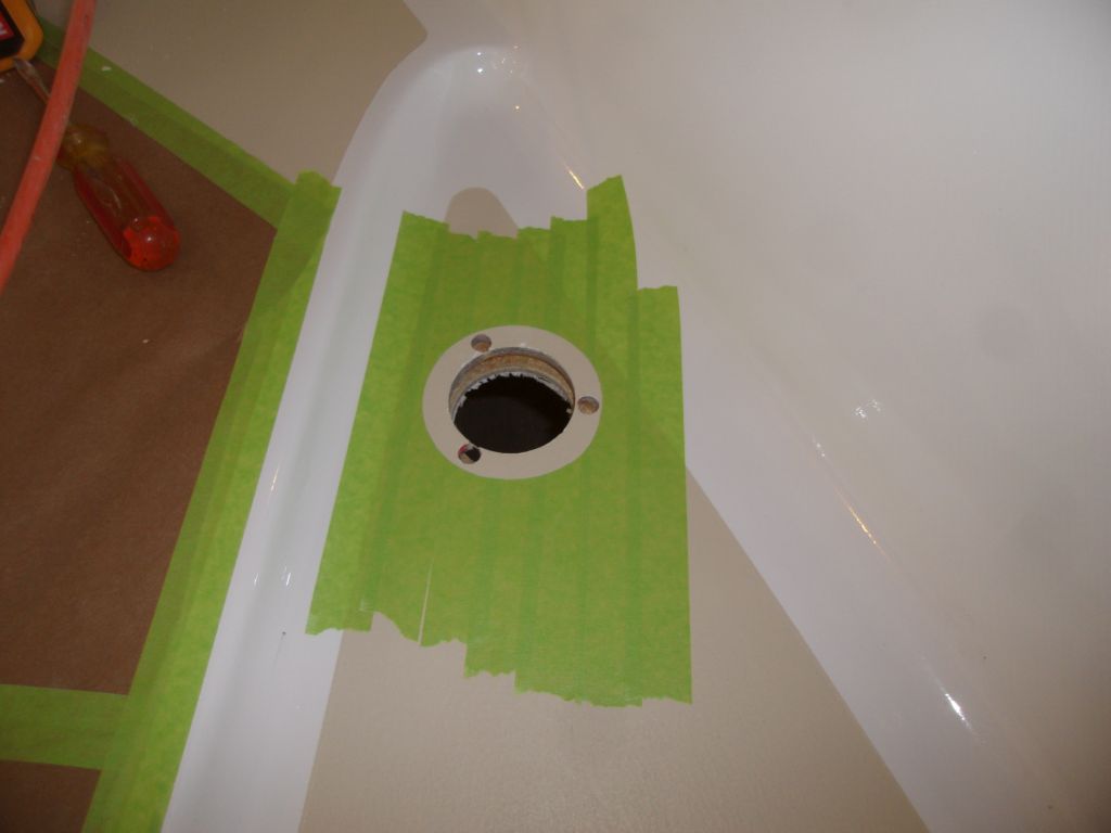
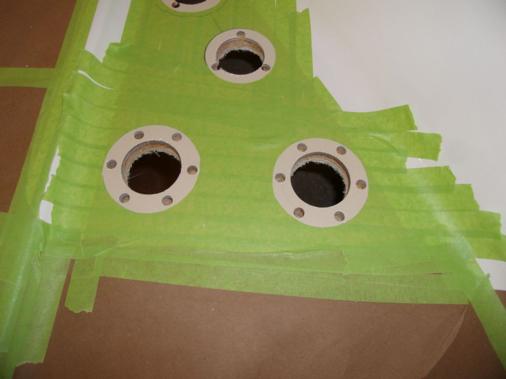
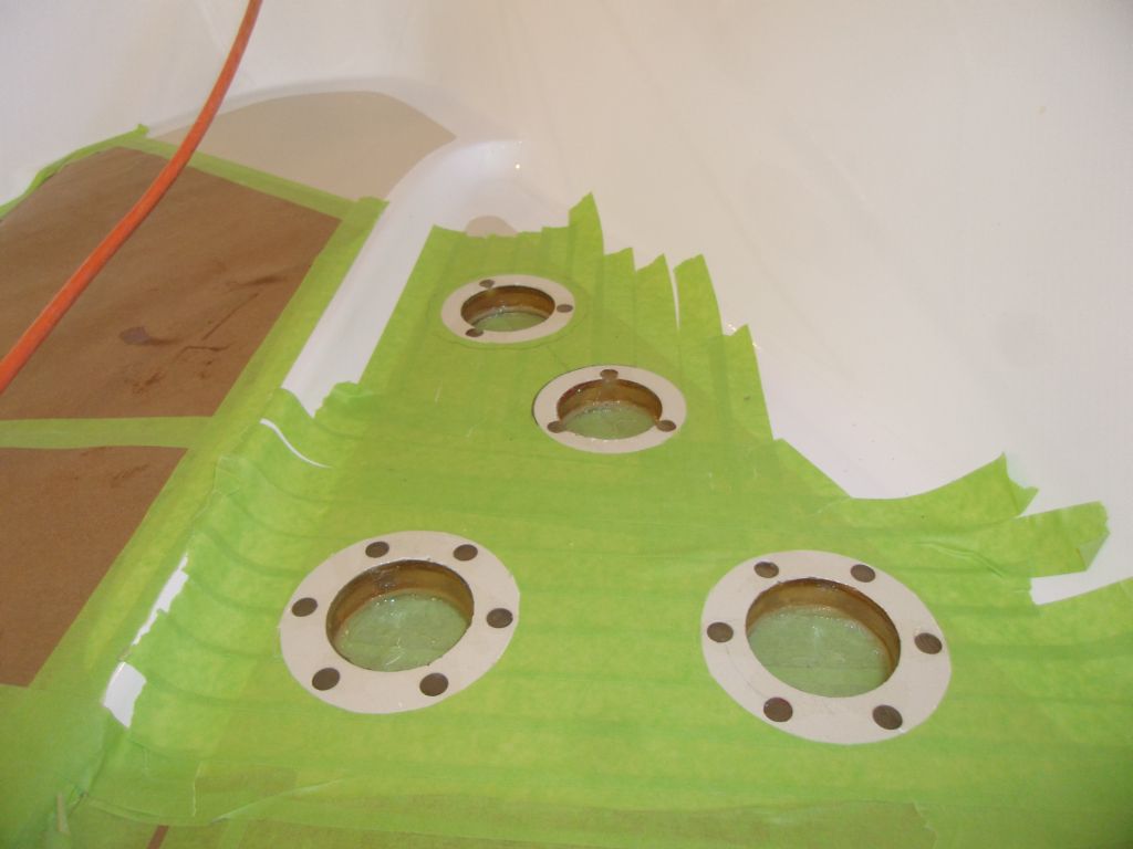
With all the openings prepared, I masked over the holes
from belowdecks (only the large holes went all the way
through the decks; the drilled openings at the fastener
locations only went as far as the inner skin), and
installed a thickened epoxy mixture in the fastener
holes and around the perimeters of the through-deck
holes, protecting the core beyond from water intrusion. |
 |
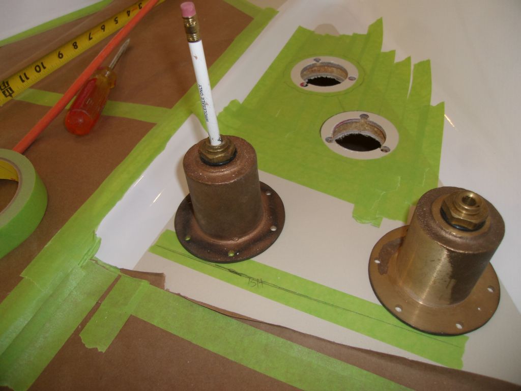
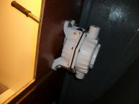
I thought it would make life easier if I pre-wired the
foot switches on the bench before installation.
While there'd be decent access inside the boat, dealing
with small terminal screws overhead in an awkward space
was something best avoided whenever possible. So I
installed wire pairs to each of the two switches.
My first go-round, with sheathed 2-conductor cable,
proved that it was too hard to snake the flat cable
through the bronze nut at the bottom of the housing, so
I switched to individual wires, leaving enough slack for
eventual routing to the windlass solenoid that I'd later
mount nearby.
The first photo shows how the housings and switches
eventually work together, with the deck in between, and
the second photos shows all the components ready for
final installation. |
 |
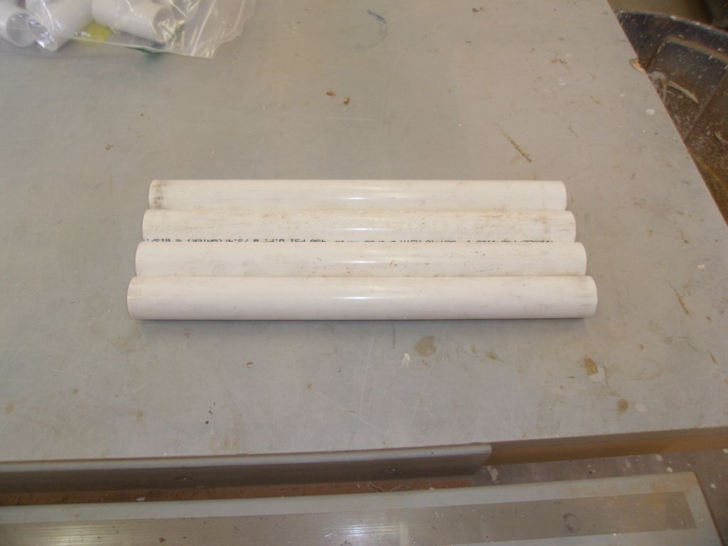
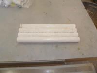
We wanted some sort of sturdy, permanent boarding
ladder, as the overall design of the boat, with her high
bulwarks and coamings, made ingress and egress to a
dinghy more challenging than on some boats. Over
the years, I'd determined (probably) that the best bet
was going to be a permanent ladder mounted to the
transom, but how exactly to configure this--and then
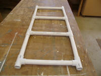
have it built--required a mockup. I thought maybe
I could build a "ladder" out of plastic pipe to serve as
a realistic template for the final thing.
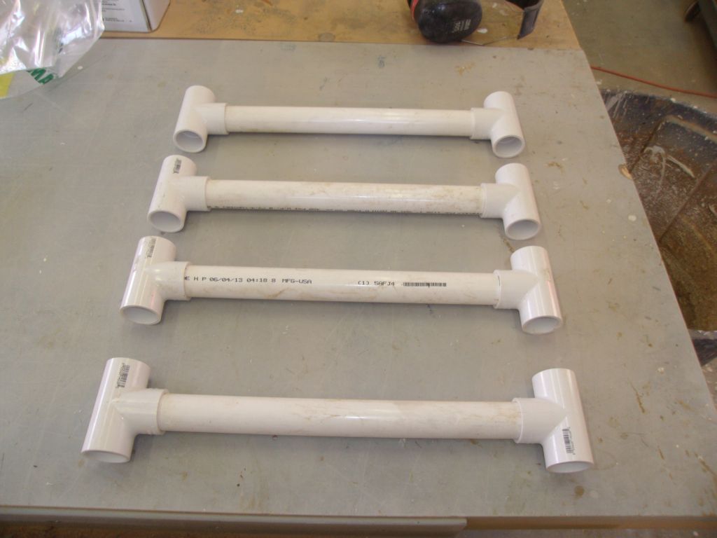
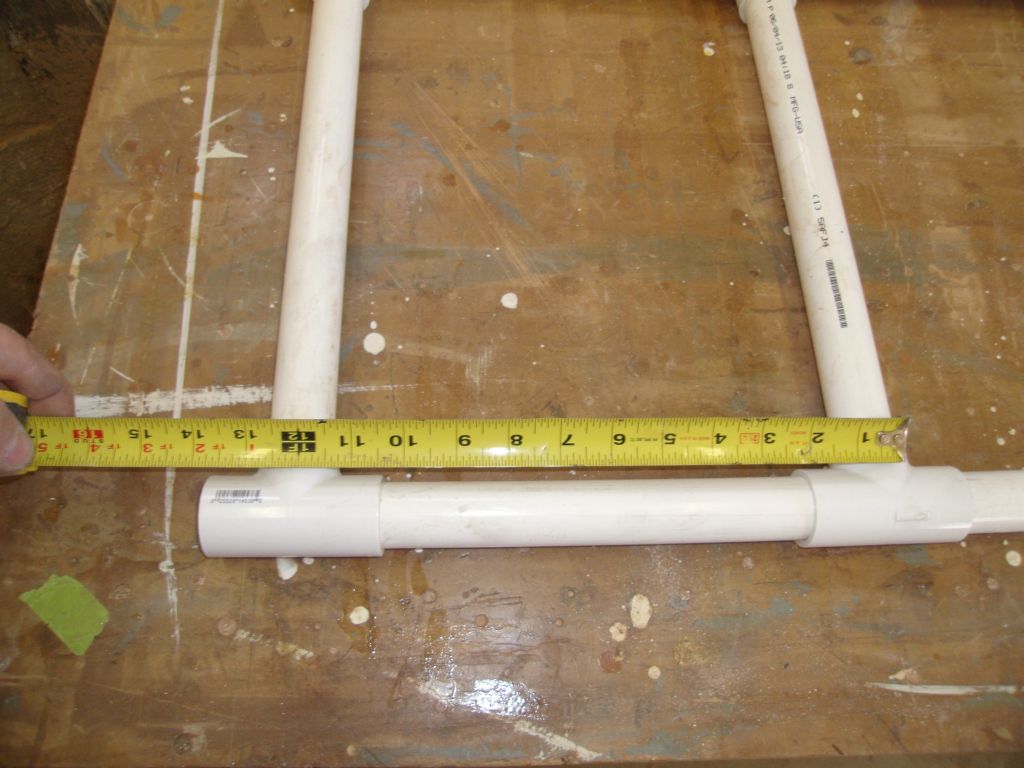
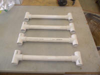
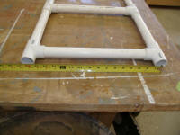
To start, I made some basic measurements to determine a
ladder width and tread spacing that worked, both with
the shape of the canoe stern and with the eventual
landing points on the caprail. It looked like
about 16" between vertical rail centers would be good,
with a 12" tread spacing, so I prepared various pieces
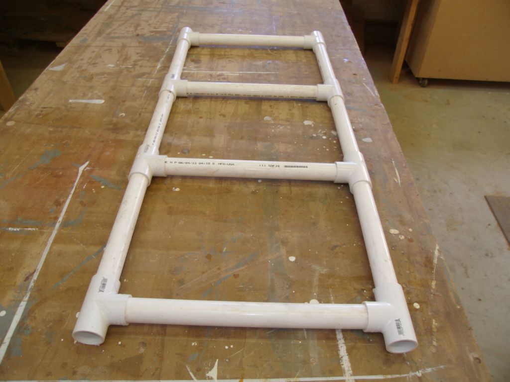
of pipe to the appropriate dimensions, using T
connectors to put them all together into a 4' long
starting section. |

 |
This was the easy part. The hard part would be
determining the design of the top section, and how to
mock it up (if it was even possible), and how and where
to land hull supports for the lower section of the
ladder. I played around with my little ladder
section for a while, attempting to visualize the next
steps that I'd continue soon, but for now the day was
done. |
| |
Total Time Today: 6 hours
|
<
Previous | Next > |
|
|