Project Log: Saturday, August 18, 2012
Starting with the easy tasks, I tied up the exhaust hose loop
inside the cockpit coaming, securing the hose to the
wire tie mount I installed earlier. |
 |
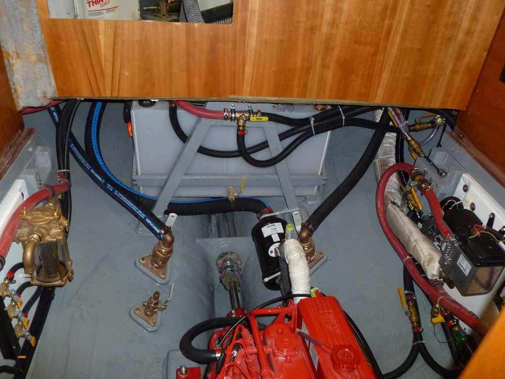
Growing weary of constantly opening and closing the
after end of the engine room, with the requirement to
remove and store not only the floorboards but also the
interim supports and the heavy after cross beam--not to
mention the increasing discomfort of access therein--I
decided to finish up a couple final tasks in the area,
which hopefully would limit my need for future access to
those areas.
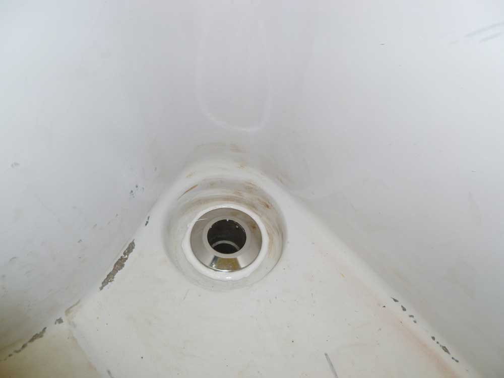
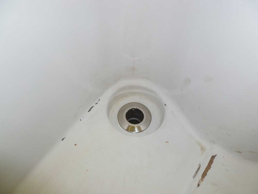
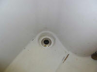
The last "major" installation in this tight area aft of
the engine room proper was the cockpit scuppers.
Preparing ahead for this installation, I'd ordered hose,
clamps, and new scupper fittings, so the task was not
overly challenging--though access, particularly on the
busy port side, fell somewhere short of easy or fun.
While I would normally choose to wait till after
painting to install hardware fittings, in this case the
always-developing order of the project was demanding
that I complete these installations now. I'd just
paint around the scupper fittings when the time came.
In the new cockpit configuration that still lay ahead,
these fittings would be hidden from view in any event.
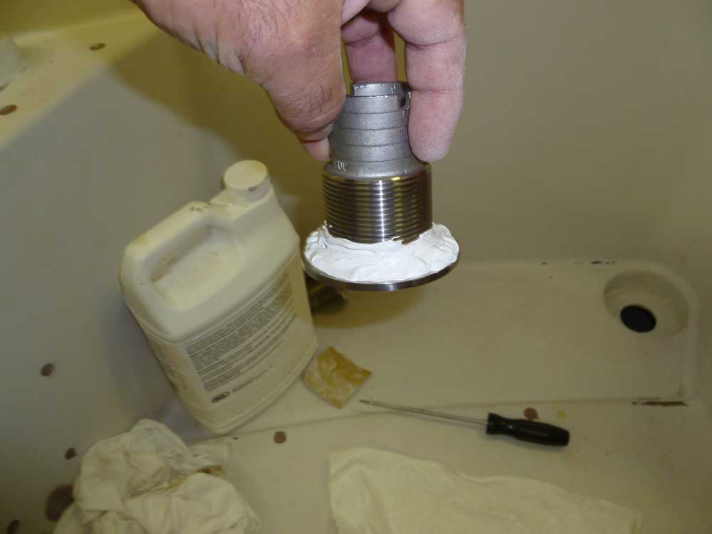
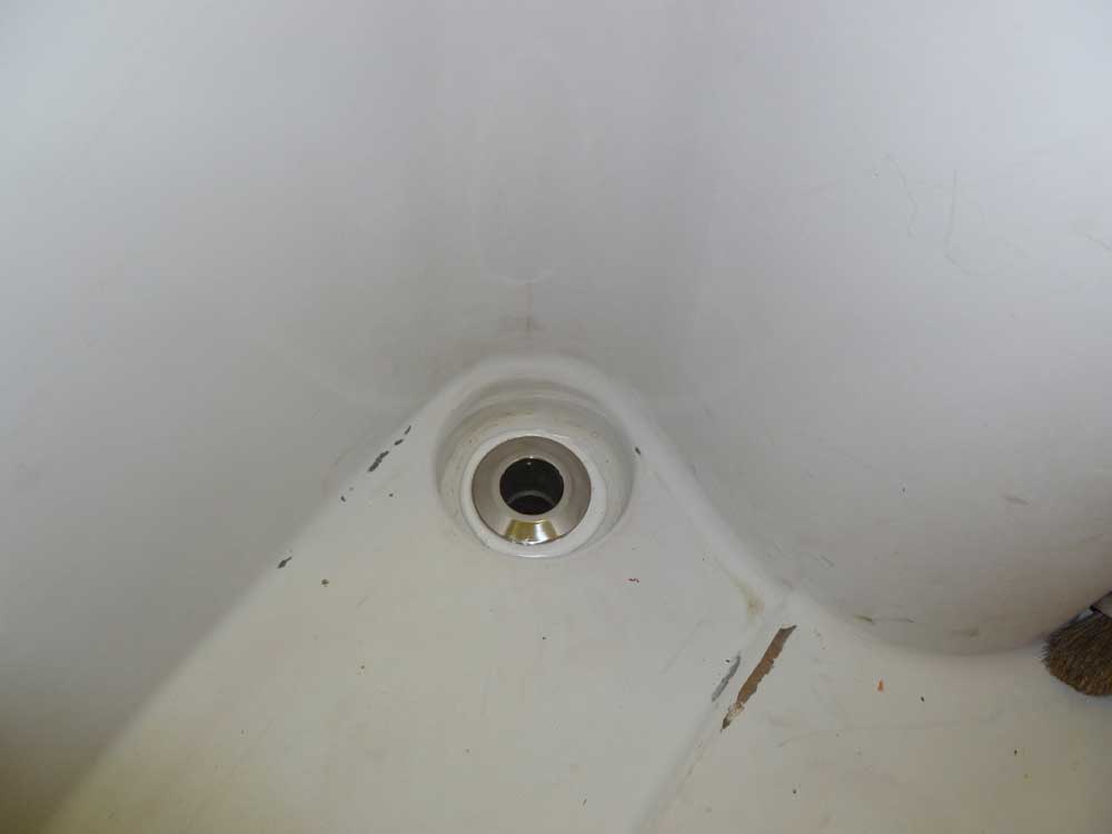
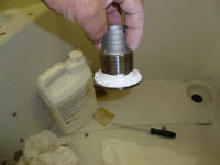
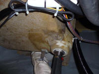
I chose stainless steel barbed fittings for the job.
After cleaning up the molded-in recesses for the
scuppers, I applied heavy beads of sealant to the
underside of the flange and portion of the threads, then
pressed the fittings into place from above. |

 |
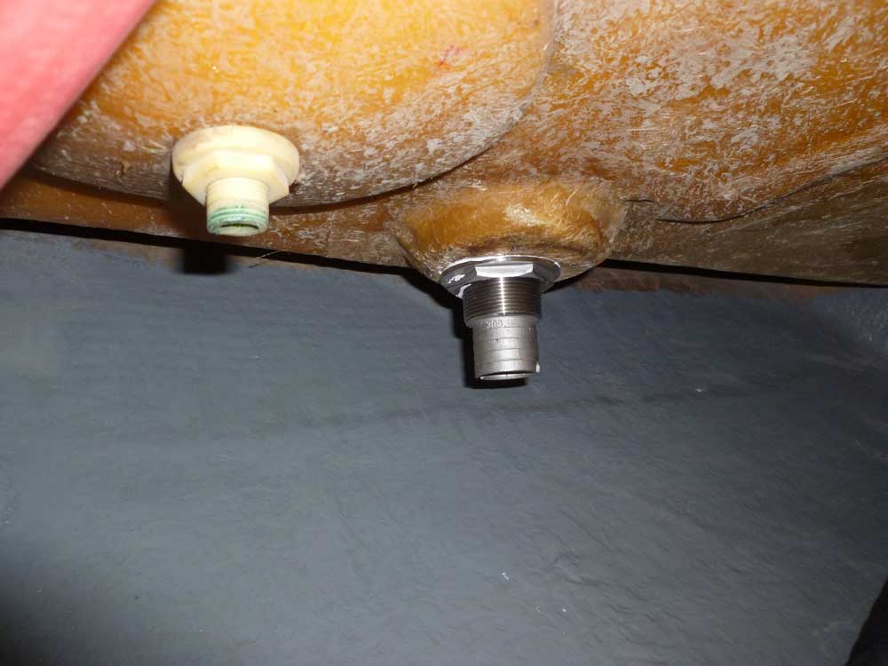
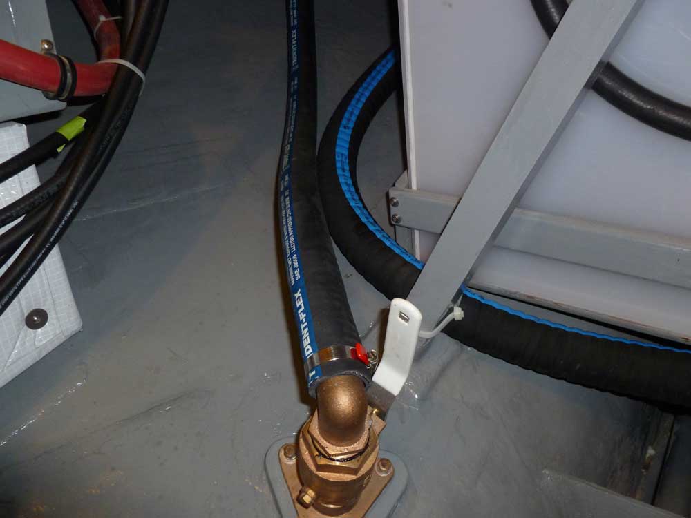
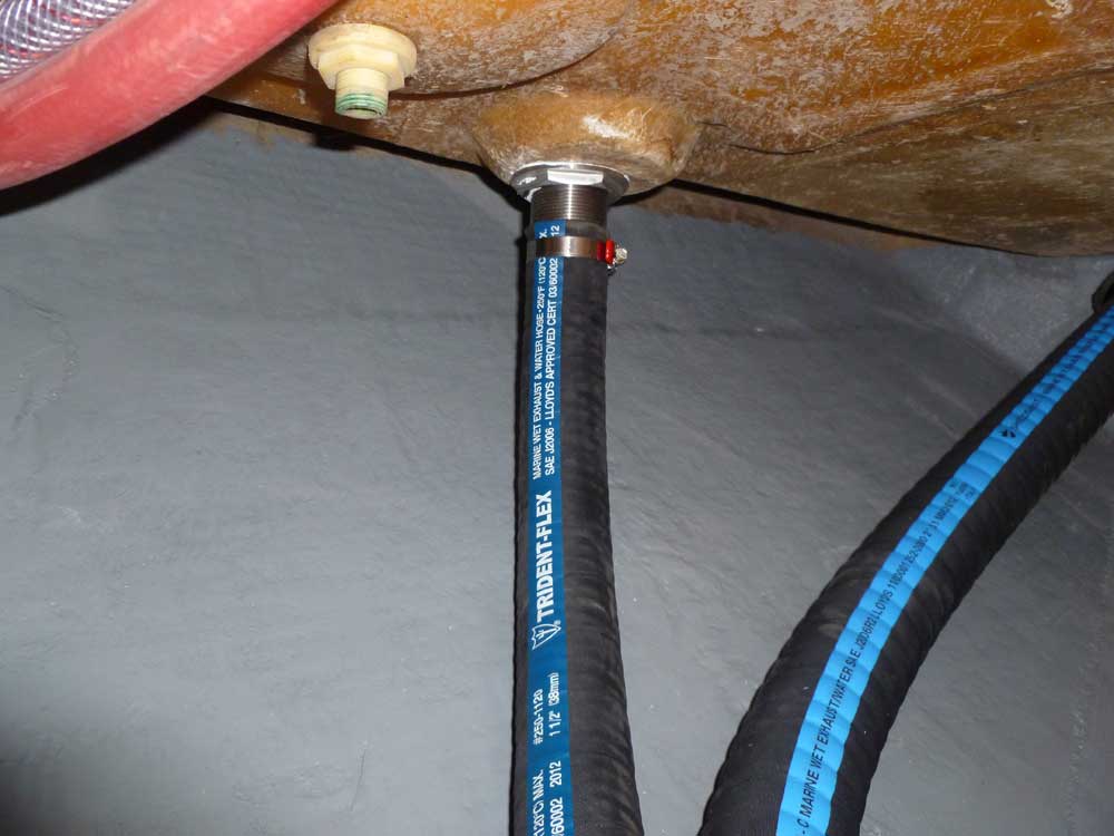
From below, I threaded on the securing nuts and
tightened them, holding the hose barb with locking
pliers while turning the nut with a wrench. Afterwards,
I cleaned up the excess sealant above and below as
required. |


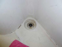 |
Using 1-1/2" ID wire-reinforced hose, I cut and
installed the simple hose runs. Later, to keep out
debris, I taped over the scupper openings on deck.
|

 |
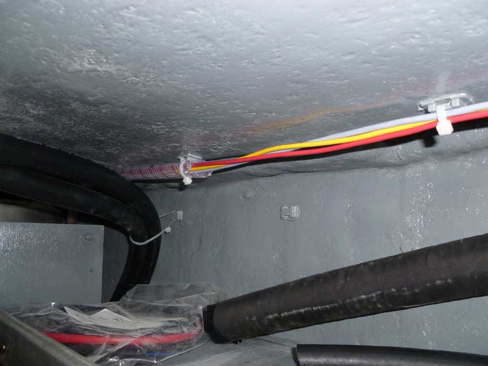
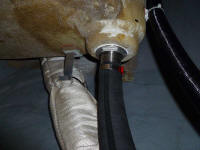
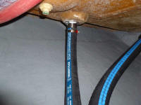
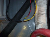
The wires from the autopilot pump and rudder feedback
sensor, which I'd led through a chase leading forward
from the after steering room, were dangling loose and
needed to be dealt with now. This led me to
consider the location for the autopilot computer box, to
which these wires would ultimately connect. The
logical and convenient location for this was inside the
port utility space, outboard of the steering console.
To lead the wires safely to this area, I prepared a
length of hose as a conduit, and fed the wires through.
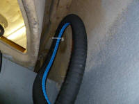
The autopilot pump's built-in wire harness was not long
enough, so I extended it with #12 wire, which suited the
amperage needs of the length of the run according to the
manual. In addition to my normal heat-shrink
connectors, I covered the splice with an additional
section of heat shrink, seen before installation in the
lefthand photo below.
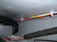
The rudder sensor wire was abundantly long, and required
no extension. Friction within the hose made it
surprisingly time-consuming to feed the three wires
through despite plenty of inside diameter.
I led the new conduit from the space beneath the cockpit
over to the port utility space, keeping it clear of
obstructions. Then, I led the wires forward to
where the autopilot computer would be mounted, and
secured the wires throughout their runs as required. |
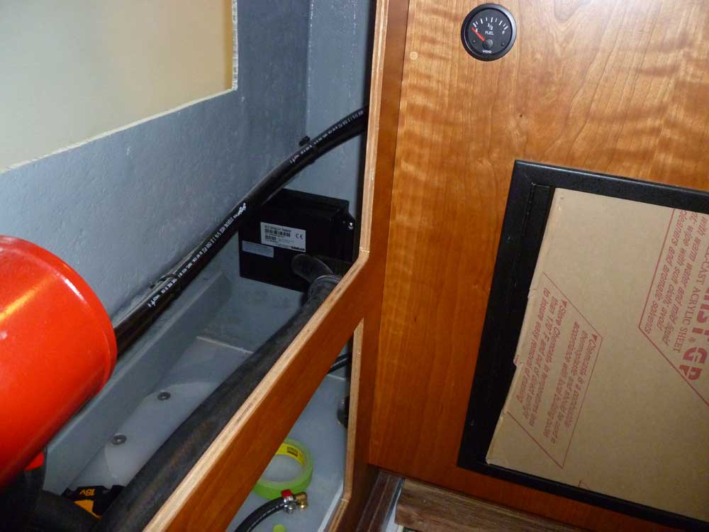
 |
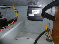
I mounted the AC12 autopilot computer in the chosen
space, which offered reasonably good access for various
wiring connections. I'd work on that in the near
future. |
 |
| |
Total Time Today: 4.25 hours
|
<
Previous | Next > |
|
|